Fairbanks-Morse 31A18

Naturally, as things progress – engines got bigger.  For Fairbanks-Morse, the 31A18/31AD18 was the largest production engine they made…at least until the 1960’s…but we will get to that later.    Fairbanks-Morse introduced their line of 31A engines around 1945 or so, calling them the new “En-bloc” engines, meaning “as a whole” in the dictionary.   While previous FM engines were made of various castings, bases, liners, air box, exhaust belt, etc., the new 31A line used a one-piece cast block, in which the cylinder liners went into (not on top of like earlier models). The cam and main bearing pockets were cast right into the block, ensuring perfect alignment every time (or so they touted), as well as featuring an integral oscillating scavenging blower.   The 31A series was offered in a 6 ¼” and an 8 ½” bore for marine and stationary service, as well as a giant 18” bore engine for stationary power generating service, and thus the 31A18 was born.

Fairbanks Morse 10 Cylinder 31A18

The 31A18 used an 18” bore, with a 27” stroke, rated at 277 RPM.   FM also offered the 31A18 in a dual fuel model, the 31AD18 – which used diesel as a pilot fuel for natural gas operation.   The engines were offered in the following configurations:

– 6 Cylinder, 2100HP, 140,000lb/143,000lb (31AD18)
– 8 Cylinder, 2800HP, 193,000lb/197,000lb (31AD18)
– 10 Cylinder, 3500HP, 247,000lb/251,000lb (31AD18)

End cutaway view of the 31AD18

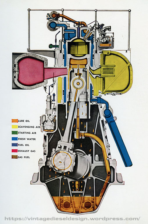
One of the few options offered was in way of the scavenging blower – The engine could be equipped with an oscillating vane blower, or none at all, with the scavenging air being supplied by a separate motor driven blower in the plant.   It appears most applications went with the separate motor driven unit.     Lubricating oil was supplied by a duplex system with an engine driven gear pump handling piston cooling, main bearings, crankpins, camshaft, injection pumps and blower (if equipped).  A separate pair of Madison-Kipp lubricators driven off the main camshaft supplied oil to each cylinder liner wall by means of 6 lines going to each. The camshaft also chain drives the fuel oil service pump.  Jacket water cooling is handled off a main header (remember, there is no internal water passages in the cast block) on the lower potion of the block, up through the liners and heads, and out through an upper header.   The engine has no water pumps of its own (common in large stationary engines), with separate motor driven pumps for the closed loop soft water in the engine, and a raw water system for the heat exchangers.  

Main casting of the 10 Cylinder model. Note the casting line between the first 4 Cylinders and the last 6. The blocks were cast as 4 Cylinder blower/non blower sections and 6 Cylinder sections.
The 31A18 used a rather unique piston. While it was not a floating piston, it did in essence use a carrier, however it was bolted in place through the skirt. The crown was a separate piece with studs, which held it all together.

The 31A/31AD18 were essentially the same engine except for the dual fuel equipment.   In addition to the standard equipment, the 31AD18 used an additional chain driven upper camshaft to control the gas admission valves, supplied by a separate header on the top end of the engine. 

The rather unorthodox method of driving the upper camshaft and fuel pump.

Around 1955, Fairbanks Morse added to the 31A18 line, by introducing a 12-cylinder option, putting out 4200HP.   Production of the 31A18 lasted until the late 1960’s – well past the production of all of the other FM engines that were not model opposed Piston models.  While FM does not support the 31A18 line anymore, there are still numerous examples of these engines still in service in various municipal power plants.   While the 31A18 family was the largest production Fairbanks Morse engine, it was not the largest. That honor would go to the 38A20 Opposed Piston engine.

A pair of 38AD18 engines in an unknown power plant. For the life of me I can not find the source of this photo. If anyone recognizes it please let me know so I can properly credit it.

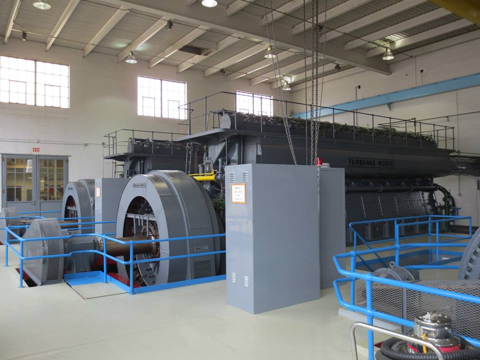
Midway Island, part of the Midway Atoll in the Pacific is home to a small power plant with a pair of FM 31A18’s. Check out this link for photos of the Midway power plant. Note that this engine has the attached engine driven blower.

Midway Island Power Plant Photos

FM 31AD18 running at the Rochelle Illinois power plant. Note the large grey pipe coming up from the floor in the front of the engine, this is the air intake, as this engine does not have the attached blower. This plant is home to many old engines including FM’s, Worthingtons and Nordbergs. Video from youtube user dzlrod

See Part IV on our Delta Power Plant tour for more 31AD18 photos.
https://vintagedieseldesign.com/2020/12/01/delta-municipal-light-power-part-iv-fairbanks-morse-31a18/

As always, I welcome and and all comments, additions, corrections and anything else.

Welcome!

Welcome to Vintage Diesel Design!

After spending the last few years working in, around, on and near several styles of old iron, I felt it was time I sat down and start doing some documenting.

Over the last 12 years, my main job has been working on the former Lehigh Valley Railroad tugboat Cornell.   Cornell is powered with a WWII vintage Cleveland Diesel 16-278A engine.   It was from here that led me into the Maritime industry where I met several amazing people whom I now call good friends, sharing with me vast tracts of knowledge on many areas, but specifically surrounding old engines – A lot of which I hope to cover here. 

Tug Cornell doing a towing class in 2018

Working on the Cornell sparked my interest into doing research on the Cleveland Diesel Engine Division of General Motors – One of WWII’s largest suppliers of diesel power.   Cleveland has been gone since 1961, and so little has been written about it over the years.   That’s where I started collecting manuals, tracking down old boats, documenting various engines, and the list goes on.   But that has since spurred into other manufactures, other designs and other uses of big engines outside of the maritime industry.

A portion of my manual library – This section specifically covering Cleveland Diesel.

Cornell has led to another interest – Tugboats.  I always was a railroad enthusiast, having spent a few years in the preservation world around trains and locomotives.  Well, as it turns out, the railroads were a major player when it came to tug design, starting in the 1920’s, so that led me into spending copious amount of time doing tugboat research – railroad and non-railroad.   In fact, I am even writing a book on railroad tugboats!  One day it will be finished…

The cover of my book, which will be available from https://www.garbelypublishing.com/ once I get it wrapped up.

  So, while the maritime industry will play heavily into all of this, it won’t be limited to.   I have plans to address many areas of Vintage Diesels – Stationary, Marine, Railroad…. And lots of other uses. 

A few ideas I am hoping to cover in the future:
-Fairbanks-Morse’s other OP’s
-Cleveland Diesel Engine Division (Lots to cover here! 498 engines, 358H engine, non magnetic engines, 567ATLP Repowers……)
-Engines that look like toasters
-Fairbanks 31A18
-Multiple diesels on one shaft
-Early Turbocharging
-Grey Marine 64HN9 repowers
– Engine lists: Winton, Cleveland, Fairbanks
-Vintage advertising
Something I do NOT plan on covering, are things like EMD engine development, and things of that nature, that have been done already.

Please do excuse this first post – I am still getting everything figured out here and how it all works.

Header photo – Cleveland 16-278A stationary gen-set at the Sturgis, Michigan power plant. More on this engine in the future.