Southwest of Cleveland, Ohio is the small town of Oberlin, home of Oberlin College. Like many small towns of the era, a small municipal power plant was built in 1933, utilizing a quartet of Fairbanks-Morse engines.

The Oberlin plant was featured the January 1948 issue of Fairbanks-Morse News. The plant originally featured 4 FM 33 engines: a 6 cylinder 33F12, a pair of 6 cylinder 33F16’s and a single 7 cylinder 33F16. In 1948 the first Opposed Piston engine was installed, which is still in place today. The plant was expanded in 1957 with the addition of the first 31AD18.


Today, the plant hosts 8 active engines:
Engine #1 – Fairbanks-Morse 10 Cylinder 38D 8 1/8
Engine #2 – Fairbanks-Morse 12 Cylinder 38TD 8 1/8
Engine #3 – Fairbanks-Morse 12 Cylinder 38TD 8 1/8
Engine #4 – Waukesha 12 Cylinder AT27GL
Engine #6 – Fairbanks-Morse 10 Cylinder 31AD18
Engine #7 – Cooper-Bessemer 16 Cylinder LSV16GDT
Engine #8 – Fairbanks-Morse 12 Cylinder 31AD18
Last year, Jay Boggess was in the right place at the right time, and was in town for the powerplants annual open house and was able to take and share a slew of photos. Lets take a walk through the plant and look at each of the engines. Click on all photos to view larger versions.
Engine #1
This is the original 38D 8 1/8 OP engine installed in 1948. This engine is most likely a WWII surplus engine, and is an “off the shelf” OP engine. The engine has the stock 1600HP rating, and is the only FM engine in the plant that is not dual fuel capable. Engine #1 can produce 1136kW.

This 10 cylinder OP was installed in 1948, and is a pretty run of the mill powerplant engine of the day. FM would supply their own generator as well. These 10 Cyl. OP engines replaced a lot of older 32E and 33F engines across the country in the 1950’s.

The right, or control side of the engine. FM OP’s have a very simple “Run – Stop – Off” control lever to operate them, however there is a slew of linkage’s inside that connect it all together.
Looking at the front of the engine, you can see the exhaust risers coming out of the engine, wrapped in insulation. Those FM exhausts throw off quite a bit of heat. An oil filter is on the floor in the foreground.

Unfortunately, FM, like many other engine companies did not add dates to their builders plates. While the serial number does match a 1948 built engine, it was not uncommon for new numbers to be issued on war surplus equipment.
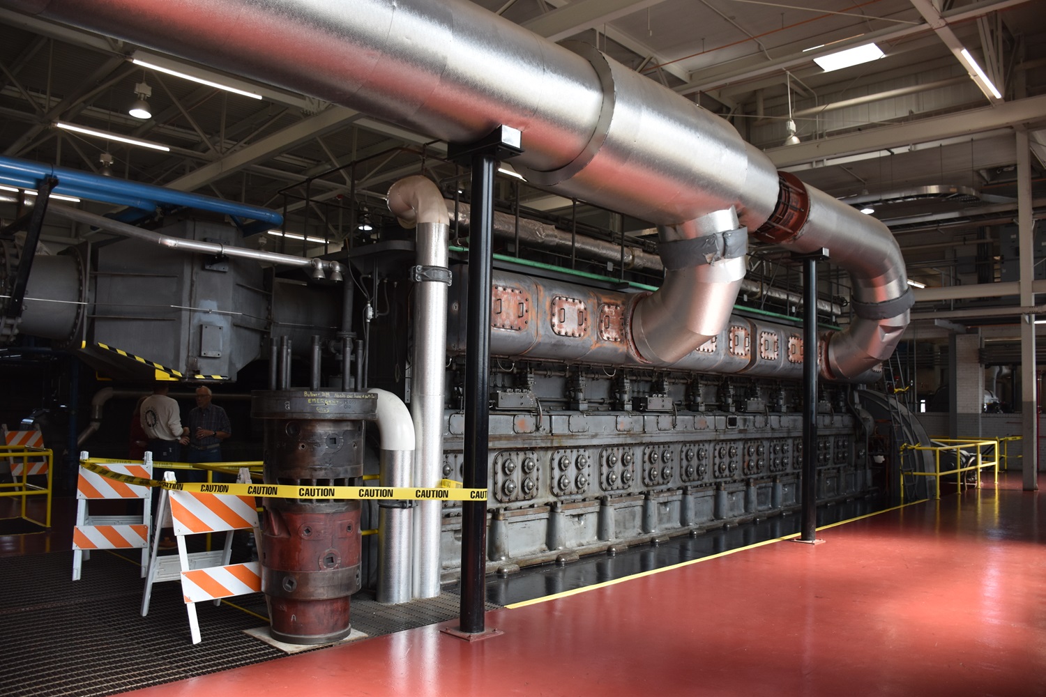
Engine #2 & 3
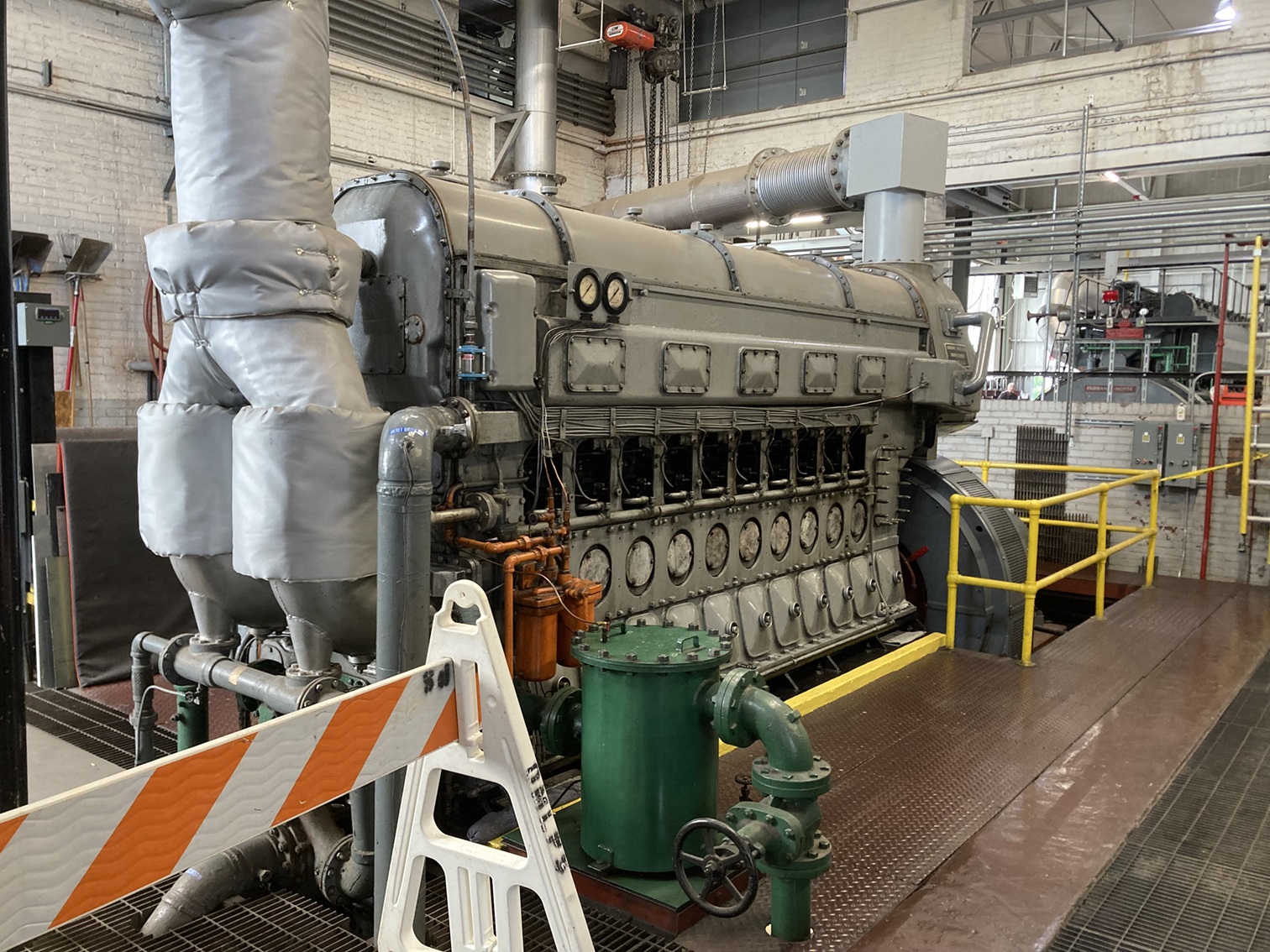
These are two sister FM 38TD 8 1/8″ OP engines installed in the plant in 2000. While based on the original FM 38D OP (like engine #1), these are the modern equivalent. They are dual fuel, thus they can run on straight diesel, or natural gas using diesel as a pilot fuel. These OP engines are rated for 3165kW each, and usually around 3600HP, thanks to the dual turbochargers.

While deep down these engines are the “same” as the original OP design above, they have a slew of modern upgrades in fuel, exhaust and emissions systems.
While FM once made their own generators in house, they now use outside suppliers, in this case, these were built by Baylor Motor/Generator group. Note that these are mounted on large skids.
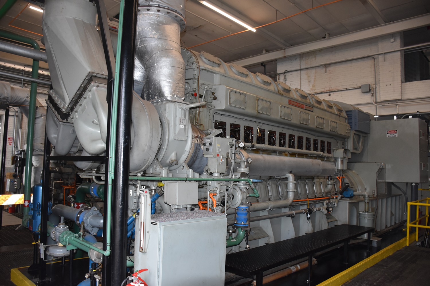
A good look at the twin turbos on these modern OP engines. Imagine one of these in a fleet submarine? The turbos feed into a large intercooler before entering the airbox.
Along with the upgrades mentioned, these higher HP OP engines also run a lot faster – 900RPM. Note the expansion tanks mounted on the plant wall, just to the right of where the exhaust exits the building.
Engine #4
The newest engine in the plant is a Waukesha 12 Cylinder AT27GL installed in 1997. I will be the first to admit I know absolutely nothing about these engines. Waukesha Motor Company was founded in 1907, and produced a line of gasoline and diesel engines. By 1955 the company was producing smaller engines for everything from airport snowblowers to small powerplants. The engine in the plant is a model that was introduced in 1985, when the company was under ownership by Dresser Industries. This engine runs on natural gas only, and is rated for 2100kW. The engine features twin turbochargers, and has a metric bore and stroke – 275mm x 300mm (10.83″ x 11.81″).
For a V engine of this size, the AT27GL is still a rather compact package when compared to the Cooper Bessemer LSV.

Note the bedplate for former engine #5 in the foreground. I will do some more homework on these engines down the road.
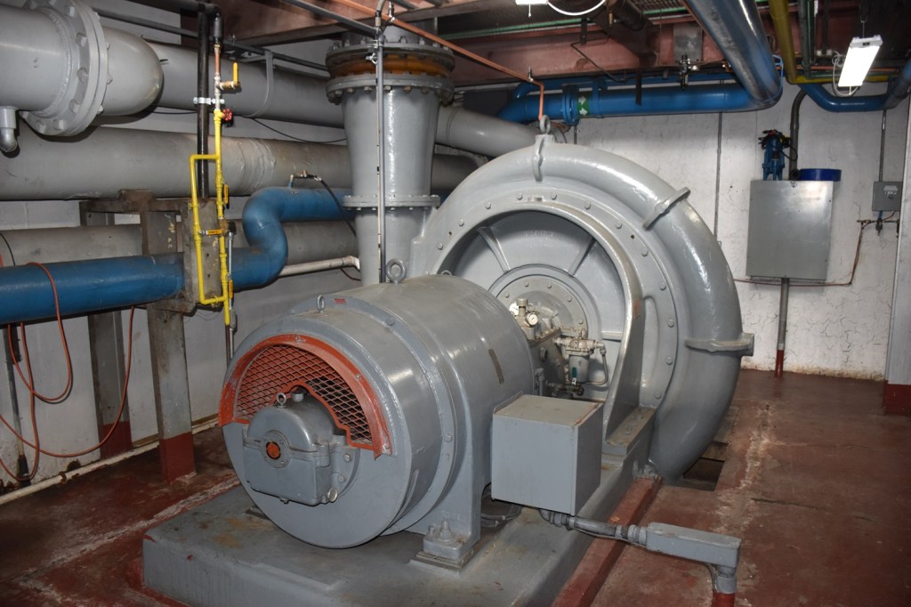
Engine #6
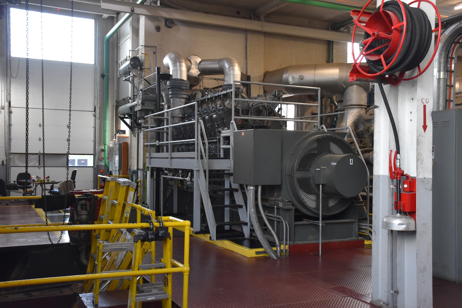
The first engine in the newly expanded plant is an FM 10 cylinder 31AD18. I wrote more about these engines on these two pages here and here. This engine is rated for 2500kW at 3500HP.
The right side of the engine. This is the air intake side. Note the oil pump located at floor level. The jacket water cooling line is coming up out of the floor. The oil pump is the only attached pump on these engines.

This is the 24″ air intake pipe coming up out of the floor, supplied by the Roots blower seen a few photos down.

A look at the data plate on this FM built alternator.

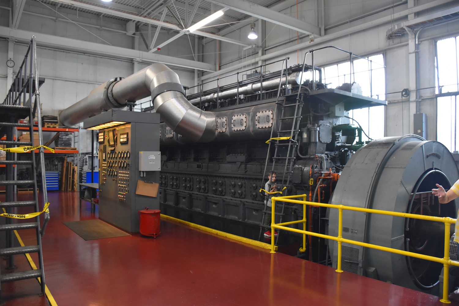
The left side of the engine, which also houses the gauge and alarm panel.
Looking up at the right side of the engine. You can see the engine control lever just below the green oil line.
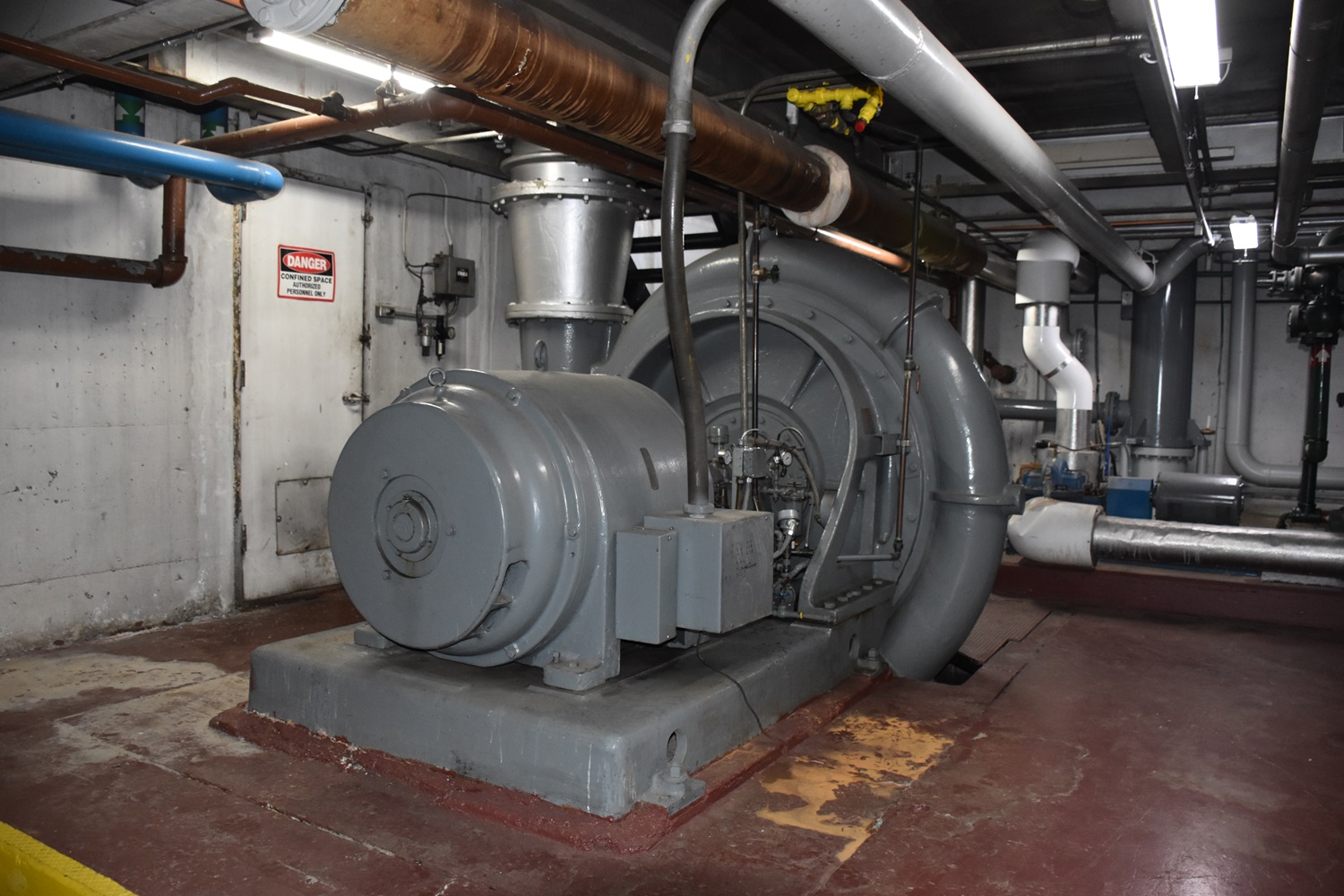
Above – The FM 31A18 engines almost always used an external, Roots centrifugal blower to provide scavenging air (they are two stroke after all) for the engines. This blower moves 17,700CFM.
Left – Engine #6 has been upgraded with a more modern gauge and alarm panel, likely tied into a computer interface.
Engine #7
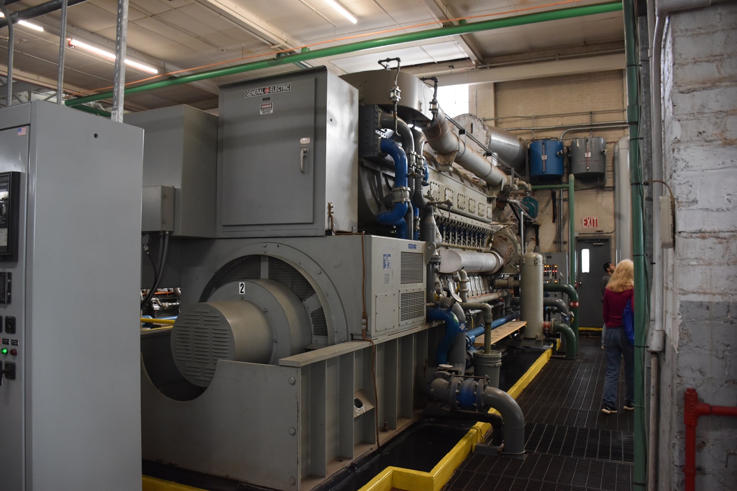
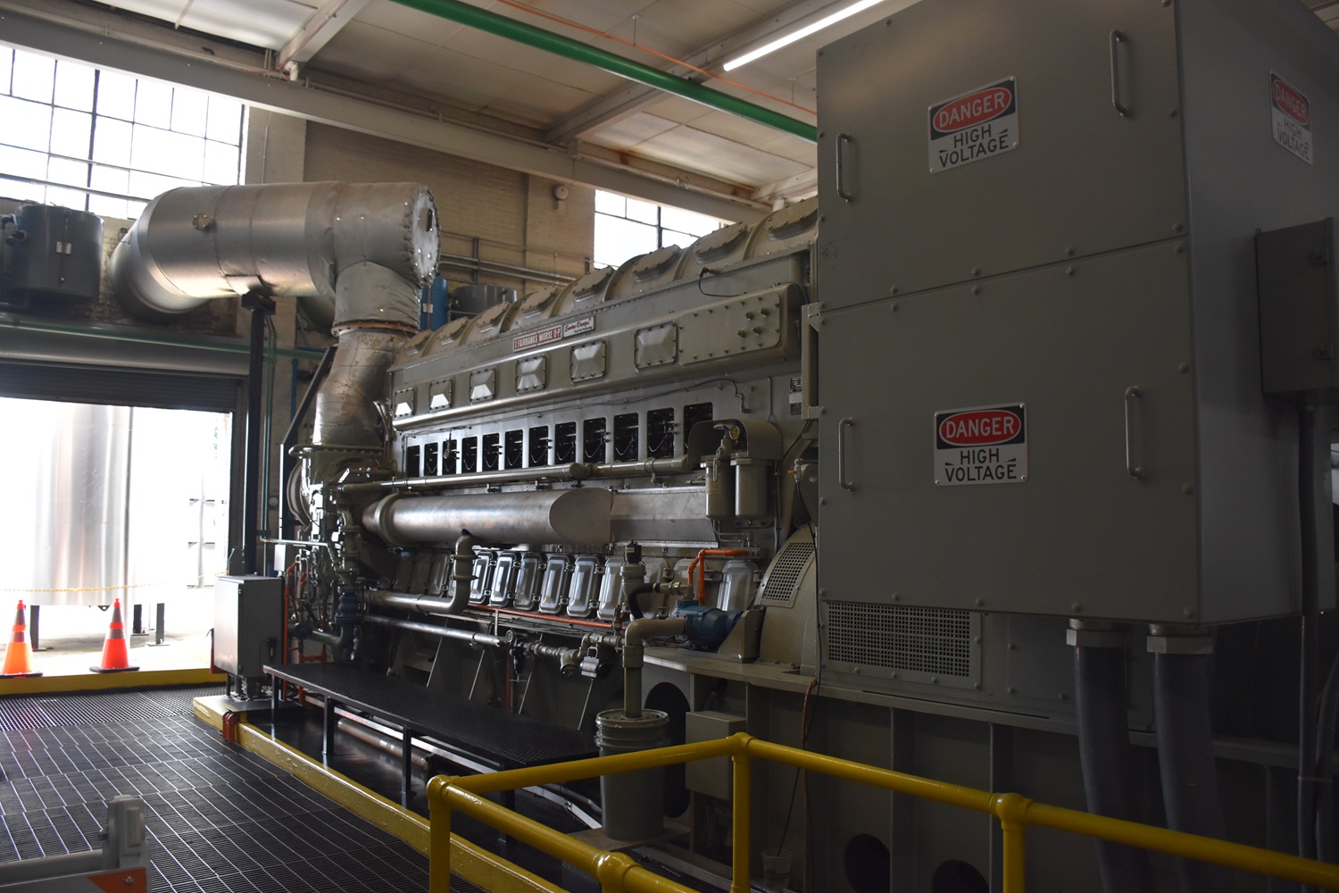
#7 is a Cooper-Bessemer 16 Cylinder LSV16GDT. The turbocharged 4 stroke LSV engine features a 15 1/2″ bore and 22″ stroke. Like the big FM’s, the Cooper-Bessemer engine is a slow speed, running at only 320RPM, but makes 3710HP and 2650kW with a GE alternator.


The Cooper-Bessemer LSV platform became a very common municipal powerplant engine in the 1950’s, and were being installed well into the 1980’s and later throughout the country, and are still common today.

A General Electric 2600kW AC Alternator was used in this specific application.

Left side of the engine. The turbocharger is centrally mounted on the above left side. Along with power generation, Cooper-Bessemer made a large line of natural gas pumping engines.

The engine tags. These engines are now supported by Cooper Machinery Services.
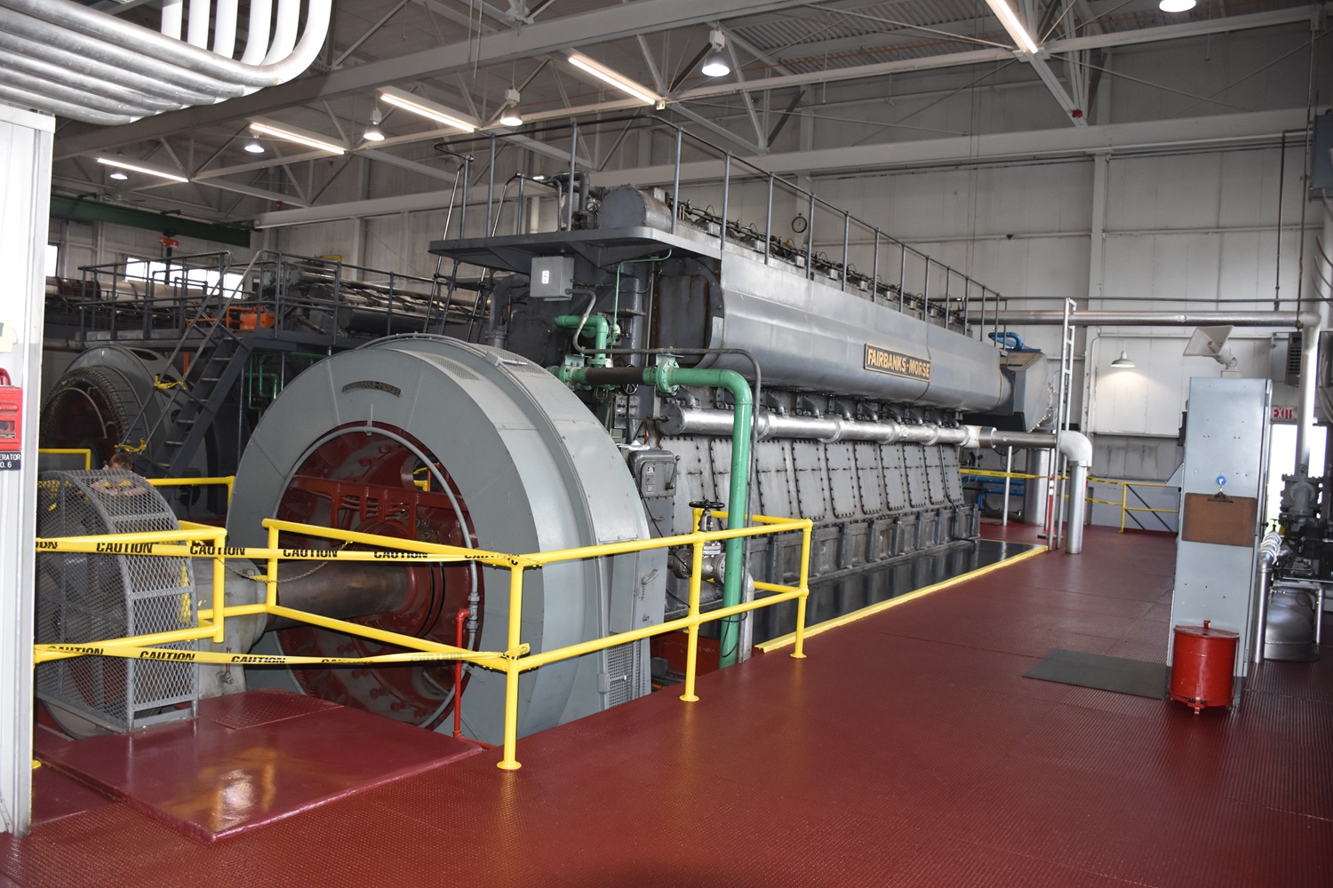
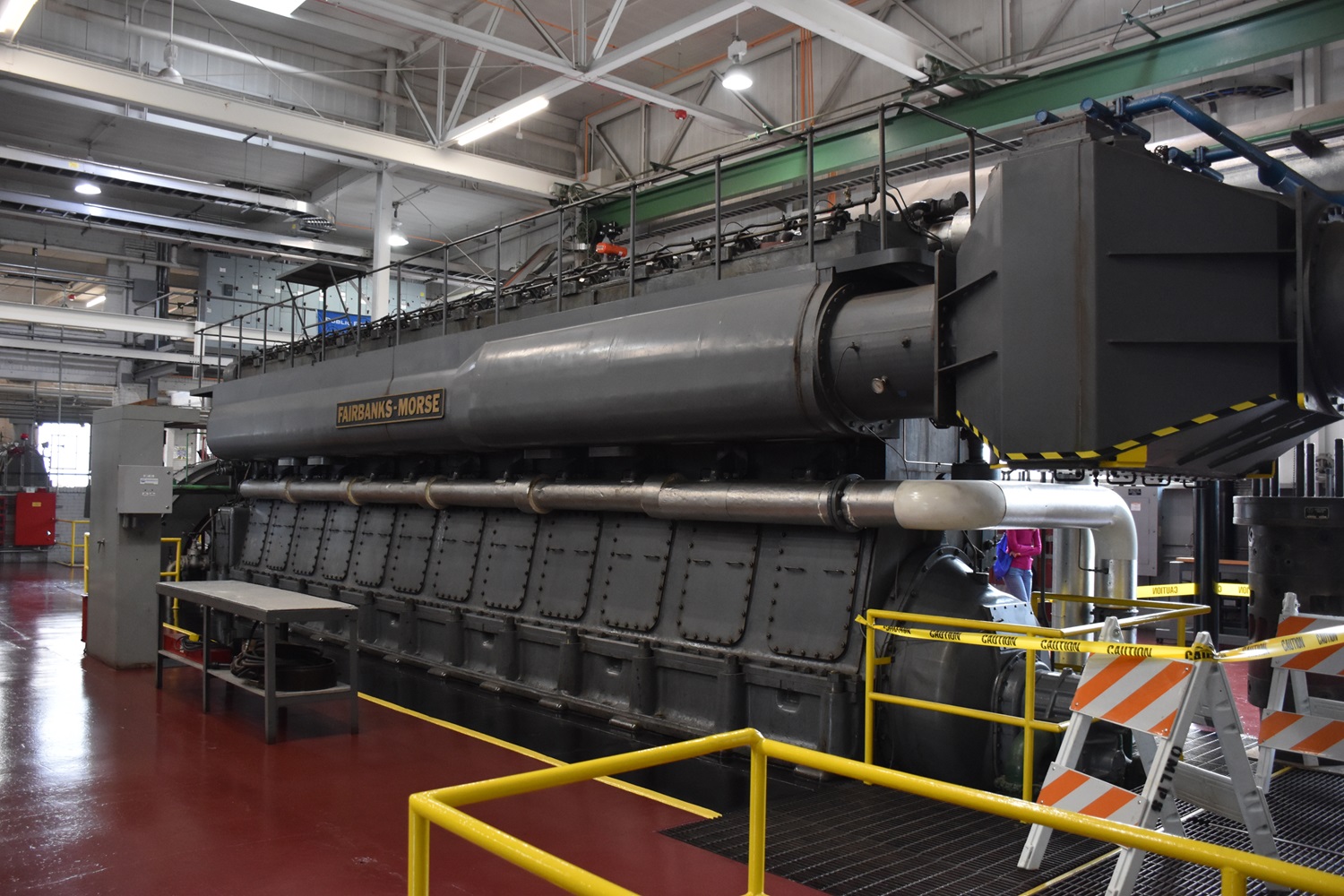
Engine#8
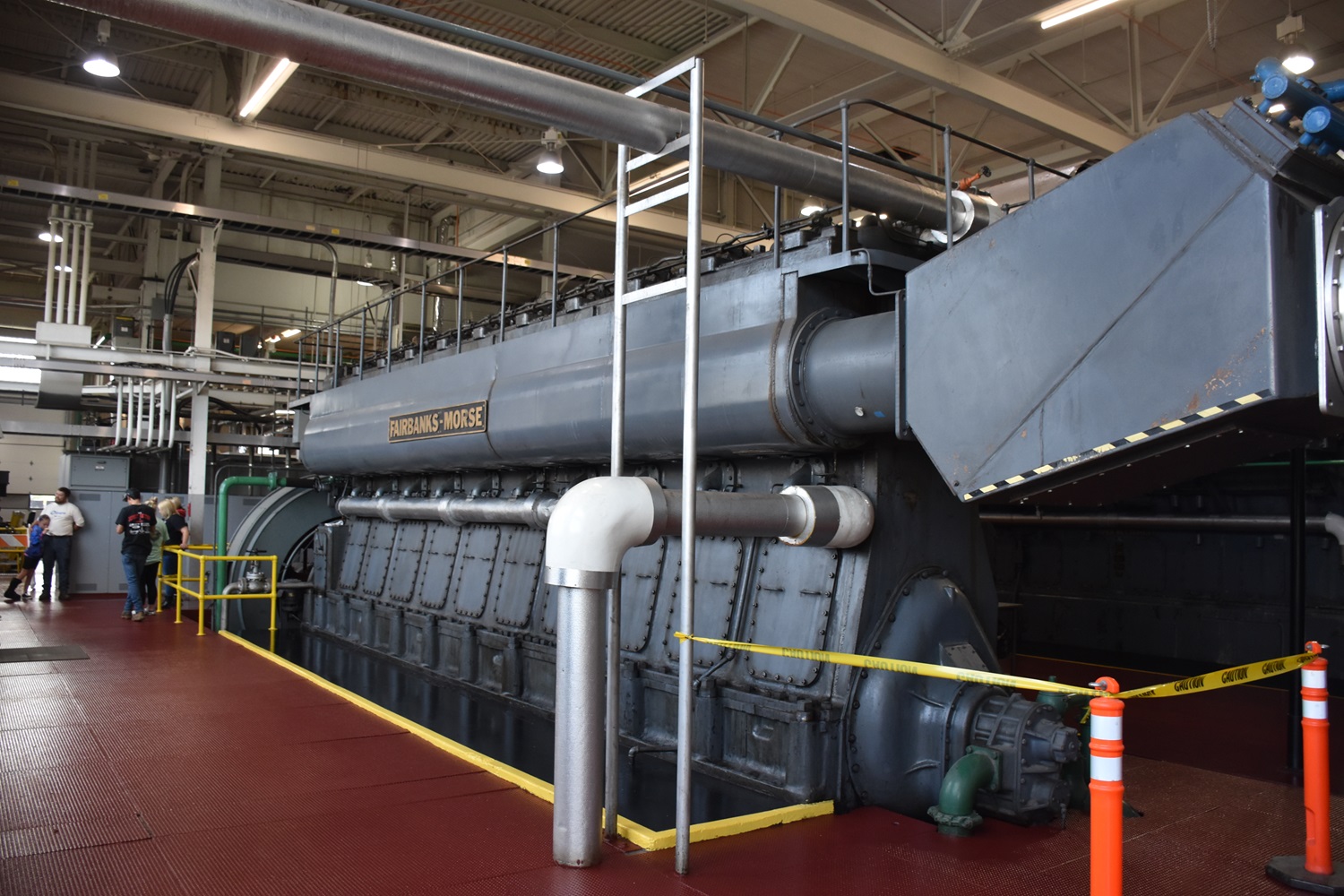
Engine #8 is another FM 31A18 – but this one is a 12 cylinder. This huge engine produces 4200HP and 3300kW, only slightly more than the more compact OP engines above, however operating at a much slower speed.

The gentleman on the left provides a sense of scale as to how big this engine actually is. This setup would be FM’s largest, successful production engine, with numerous 31A18’s still running around the world. Not bad for an engine that has not been built in 50+ years!

The generator and belt-driven exciter. Note the polished floor – municipal plants are almost always kept in top shape!
The exhaust side of the engine. A lot of times, the exhaust would be run into the floor, and run outside in a concrete conduit, however these exhaust through the plant wall into the mufflers.
Like engine #6, this one also uses the Roots blower mounted in the basement. Be sure to read Jays post on the history of Roots here.
The right side of the engine. I am not sure what the large box is on the intake side of the engine, possibly a filter housing – I have not seen it on another 31A18.

Data plates on the FM built alternator. FM was once a powerhouse in not only engines, but generators and motors as well.

The data plate on the blower. This one providing a little more (21,000CFM) then the one used on the 10 cylinder engine.
Its not super common for municipal powerplants to have lots of spare parts on hand, as most of the heavy repair work is mostly contracted out these days. Oberlin does have some though for the FM 31A18’s however.

A row of pistons, connecting rods and cylinder liners lined up against the wall.
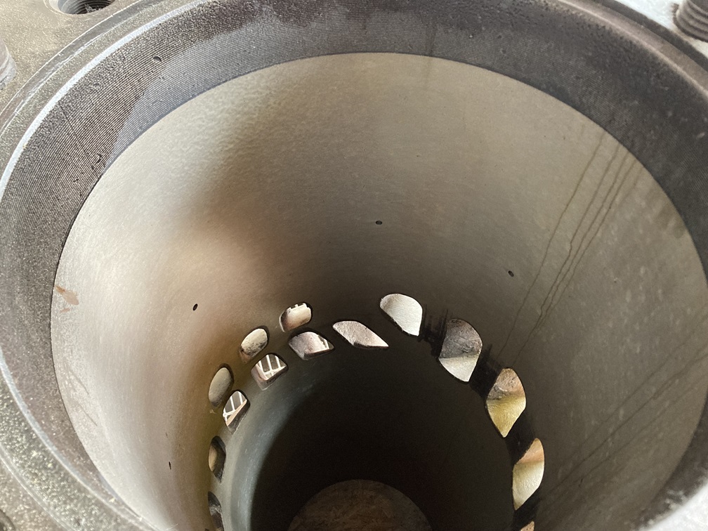
Looking down into the bore of the liner showing the intake and exhaust ports.

Some of the plants electrical switch gear.
At some point (possibly during the first expansion), a small addition was added to the left side of the plant – this is where the #5 engine originally was, however I do not know what that engine actually was.
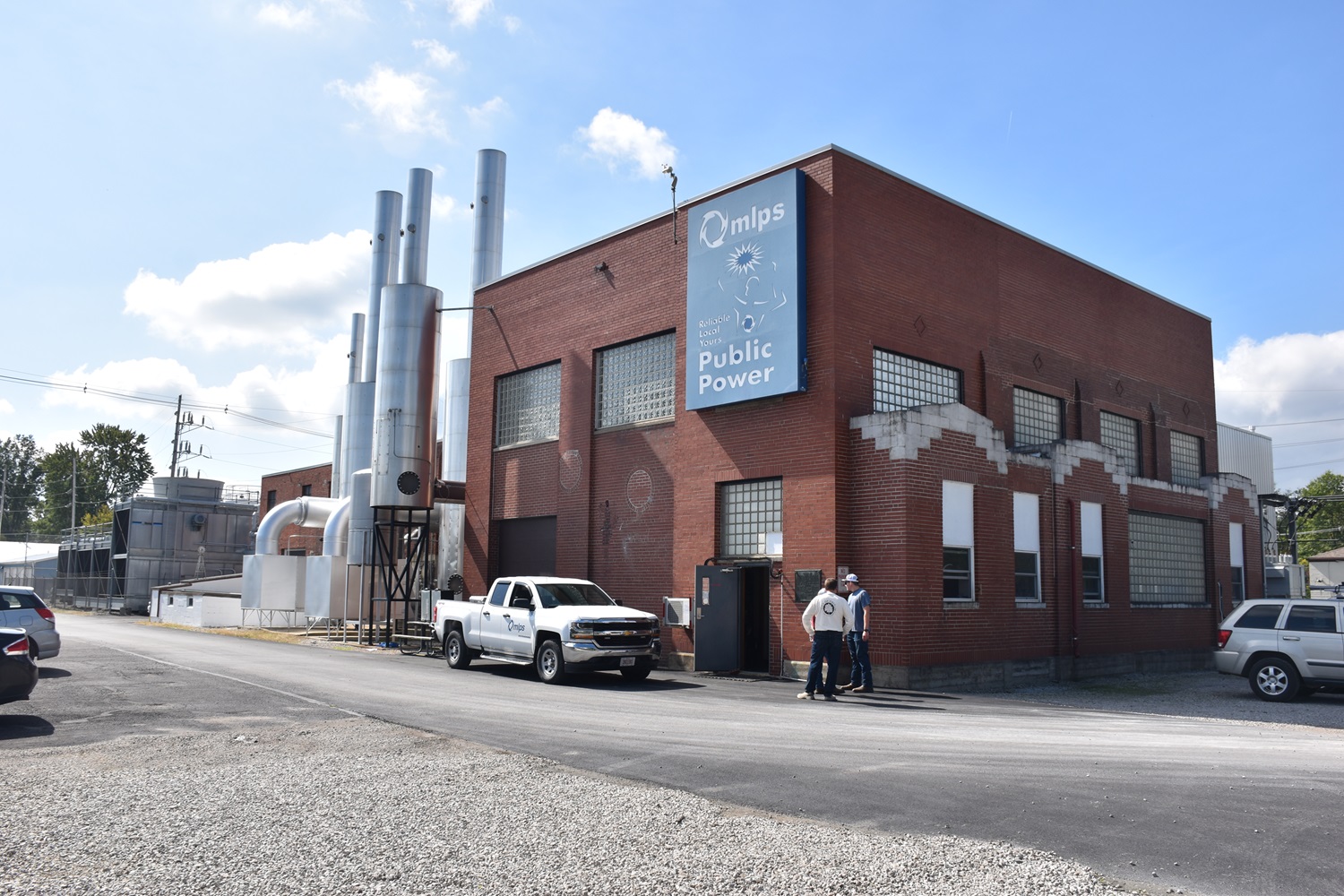
Compare this view, to the one in the FM news issue on the top of this page, you can see the small addition they added. Whoever did it should be proud, because it matches perfectly! You can see one of the cooling spray towers in the back.

The mufflers for the 4 engines in the original part of the plant. On the left is the original FM OP #1 engine, the two bigger OP’s in the center, and the Waukesha on the right. The smaller boxes towards ground level are the air intakes.

The newer part of the plant features more spartan steel construction, versus the ornate brickwork of the original.

These mufflers are for the two FM 31AD18’s, and the Cooper-Bessemer in the middle.
Thanks to Jay Boggess as always for sharing these photos!