With the help of Winton, the Electro-Motive Company pioneered and developed gasoline-electric railcars. Hundreds of these cars were built in the 1920’s-1930’s, and were an important stepping stone in the development of the forthcoming Diesel-Electric generation of railcars and locomotives.
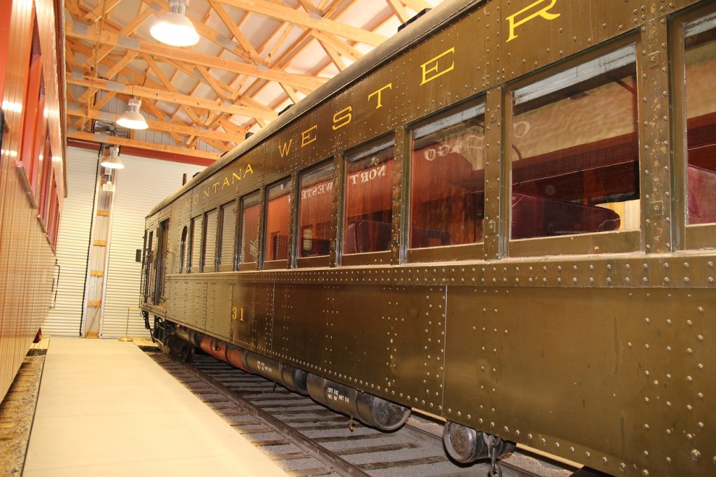
Only a small handful of these cars remain, including Montana Western #31, at the Mid-Continent Railway Museum in North Freedom, Wisconsin. #31 was donated to the museum in 1965.
The car was built in 1925 for the Great Northern Railway as their #2313, and was sold to shortline Montana Western in 1940. Only the front truck on these cars is powered.
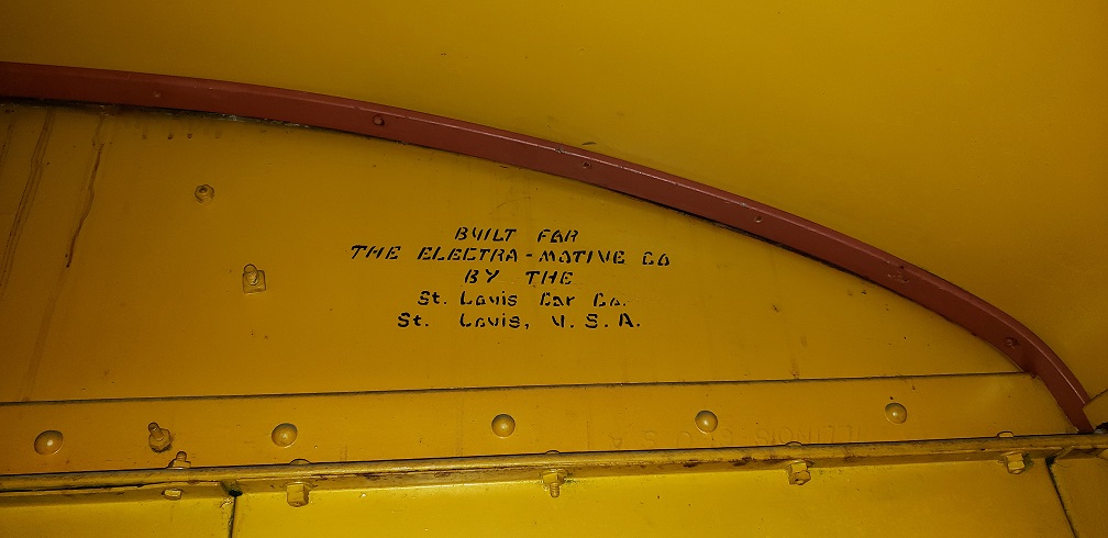
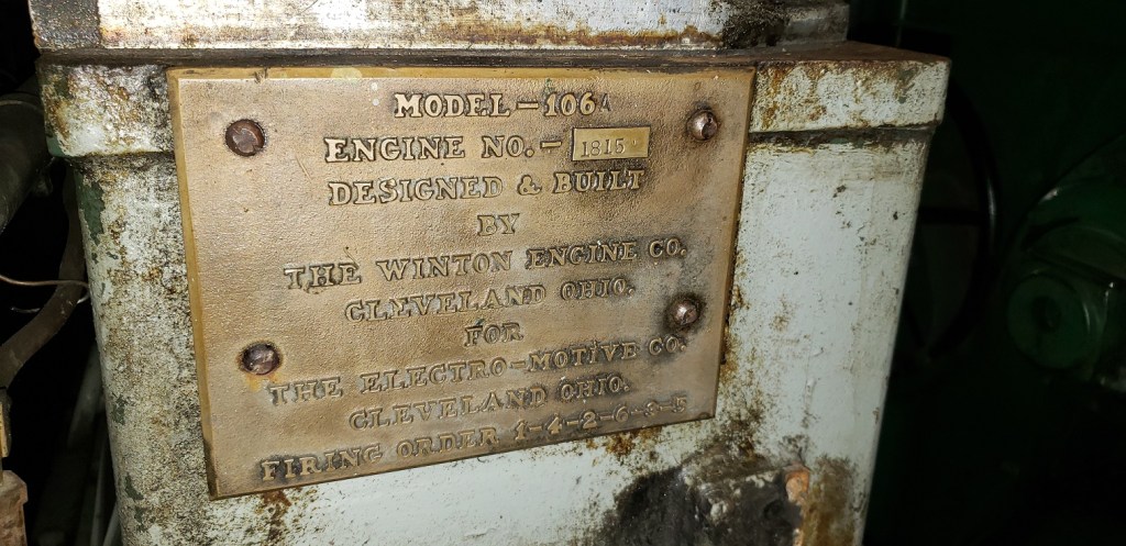
While the date on the plate is 10/1925, the car’s engine was not shipped until 4/1926, leading me to think this may have been a contract date.
Inside, the car is essentially 100% original, including these lush purple velvet walkover seats. A small smoking section is in the compartment forward of this one.
Ahead of the smoking section is a baggage room, as well as being home to the cars heating boiler.
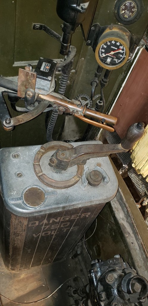
The rear end of the car features a control stand, as well as a small bathroom opposite of it.
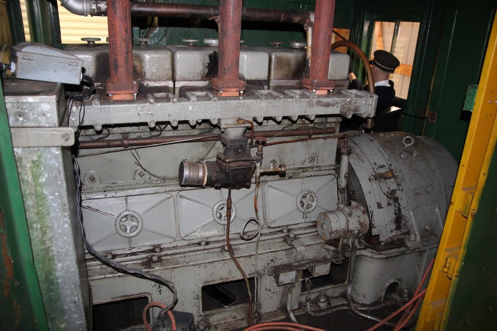
Forward of the baggage room is the engine room, home to the 6- Cylinder Winton 106A gasoline engine and control stand.
Stepping back a few feet gives us a better overall view of the engine, showing the central carburetor and intake manifold. These early engines used General Electric electrical gear. The three exhaust pipes head straight up to the roof.
Forward of the engine is the engineers corner with the various controls and brake system, note the use of a “trolley” style controller. My ears bleed just thinking of being this close to the engine!
The engine in #31 is a Winton 106A, a 7 1/4″ bore x 8″ stroke, 4 stoke, 6-cylinder gasoline engine. The engine was rated for 250HP at 1200RPM. Previous model 106 was a slightly smaller, 7″x8″ engine, rated for 200HP at 1000RPM.
What is interesting is the Winton record for this engine lists it as a 106B. It is likely this is simply a typo on the record sheets, as other engines labeled 106A are listed with the same shipping date.
Looking toward the magneto side. While you can access the cab through doors on either side, or by climbing over the generator – it is still an extremely cramped space.
A better view of the engine from the Winton manual for these engines.
Special thanks to Bill B. at Mid-Continent for arranging a look inside this rare piece of equipment. #31 is currently not in operable condition, however the museum does have a 2nd spare parts engine it obtained from Sperry Rail – once a large user of Gas-Electric railcars. Be sure to stop by the museum if you are in the area, they have an amazing collection!
One of my big griefs with setting this up as a blog format initially, was that after a certain period of time, the posts would disappear off the home page. I was working around this initially by doing a post every so often with a listing of every post.
Now, you will see on the right hand side of the page..
… a listing of various topics we have covered. In each of these pages is a sub listing of all the articles that pertain to that topic, essentially making this more of a website, then a blog.
This is the first step in hopefully a bunch of cool new things coming this year, so stay tuned! Be sure to sign up on the right hand side as well, and you will get an email (NOTE: It does go to spam sometimes!) whenever we make a new post.
Note – Apparently these pages do NOT show up when your viewing on a phone..
Happy Holidays from VDD! This post was written by guest author Nathaniel Rana.
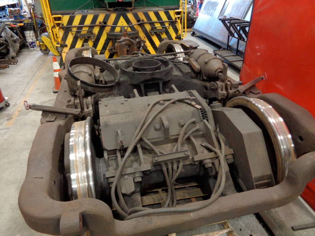
For some background, I’ve been coding a comprehensive railroad DC rotating equipment simulator which has required some in-depth technical information and research to the point I’m regularly consulting electrical engineers. I’ve gotten in the habit of learning and unlearning information on the regular, the most recent of which is the process by which Baldwin diesel locomotives with Westinghouse electrical gear handled motor back EMF. Rather than utilizing transition in addition to motor field shunts such as with GE and EMD’s rotating equipment, Westinghouse equipment in nearly all Baldwin locomotives (as well as the vast majority of Lima-Hamilton and potentially early Fairbanks-Morse low-horsepower switchers) exclusively handled motor back EMF by means of motor field shunts.
For the longest time I wondered what, if anything, made Westinghouse special. I didn’t have the means to ensure an actual answer until recently where, armed with maintenance bulletins and a better understanding of motor properties, I could finally sort this out; I had wrongly assumed that Baldwin simply took the hit to high speed tractive effort that neglecting transition would normally get you. This article will attempt to explain why Baldwin did not utilize motor transition.
Motor Background:
So, to start: Whereas EMD and GE primarily offered the same traction motor between their switchers and road power, Westinghouse used two different models for their postwar offerings. The first being the 362, smaller of the pair, was initially used on VOs and good for some 200-250 horsepower. The larger, later motor was, the 370, first used on the massive multi-engine Essl locomotive project and nominally rated for 750 horsepower, with later uprating to 900.
Fig 1 – 362D from a locomotive at SMS.
The 362 was not particularly special; it was a four pole, DC unit that was relatively light – 5,520 pounds bare motor with pinion (FM Bulletin SEC.411.5A) versus 7,000 pounds same for a GE 752 (ALCO, TP-503 1st edition). The primary use case was light road-switchers and switchers limited to 1,200 horsepower for traction and below. Of note is the high internal resistance – two to three times that of the 752 or D7 series.
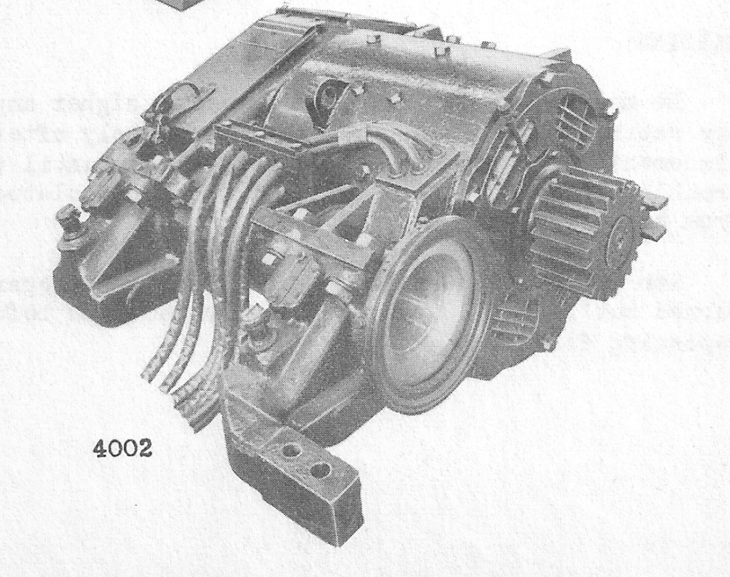
Fig – 2 – 370 motor
The 370, however, had a unique quirk as far as railroad rotating equipment went; it was the only six pole DC motor used in significant capacity for US railroad diesels. Additionally, it was capable of more horsepower than the GE 752 on introduction – 750 versus 600 or so – despite similar weights: a complete motor weighed 6620 lbs, 7400 with the gear and gearcase (Westinghouse Maintenance Instruction for Traction Motor, Type 370). It is worth mentioning that this motor also has the lowest internal resistance I’ve seen so far, slightly below that of the 752.
A quick note on motor behavior – torque of a motor is a function of amperage through the armature, and the amps drawn by a motor relies on resistance (as well as internal structure but that’s much harder to quantify). Additionally, back EMF is a function of resistance and efficiency curves – manually playing with these in my simulator it became obvious that the 362 sucked down relatively few amps and put out a ton of back EMF for any voltage applied to the motor at speed. As a result, one could expect to note that applying motor field shunts or transitions would become necessary at much lower speeds than competitor’s equipment. Let’s see how that holds up in practice.
The 362:
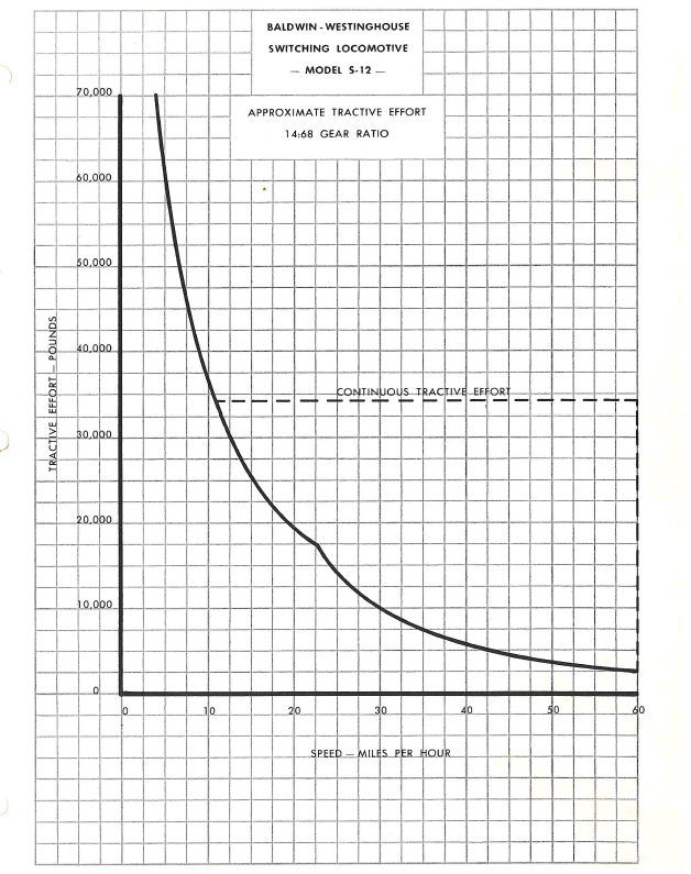
Fig 4 – S12 switcher approximate tractive effort
Immediately of note is the bump at 21mph. Having seen these charts before, I’d assumed this to be a quirk of the drawing or just the effect of motor field shunting, since before now I only had third-party diagrams to go off of. However, one of the available modifications caught my attention:
Fig -5
It specifically calls out this speed as 22.7mph – the “unloading speed” – where full horsepower utilization of the engine is no longer possible as the generator cannot safely output any higher voltage to counteract back EMF (This is why alternator-equipped DC traction locomotives had greatly simplified transition sequences – significantly more voltage available to cram into the motors). Bizarre to see it as an option, though while they could potentially benefit from transition, the application of it was less than critical on a switcher so perhaps the S12 is a poor example. So – what about something road-capable?
The Lima-Hamilton 1200 horsepower road switcher is one of very, very few 362-equipped locomotives that also received proper transition. The full sequence is two steps of field shunting followed by motor transition as the unit accelerated, per the operations manual; maximum voltage for the generator applied to the L-H engine is similar vs. Baldwin units at 1000 volts before unloading occurs.
Fig 6 – L-H 1200hp R/S TE curve
The “unloading” speed for full parallel operation is a much more reasonable 40mph. The BLH RS-12s NYC purchased following this order behaved similarly, evidently with special-order transition. In short: 362 equipped locomotives didn’t make transition because they tended to not need the high speed TE given the intended duties, but there’s no special quirks about the motors that made it truly unnecessary. Full horsepower utilization could likely have been achieved up to 60mph with an additional step of field shunting in full parallel. This leaves us with the larger road-exclusive traction motor to look at.
The 370:
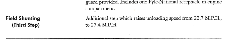
So let’s repeat what we did above, and look for the unloading corner on TE charts – I’ll use the AS-16 here, with the date of the chart being an early 1952 model giving us a unit equipped with four steps of motor field shunting, and motors permanently wired in series-parallel similar to nearly all other four-motor Baldwin units.
Fig 7 – AS16 approximate tractive effort
No corner – maybe it’s a simplified chart? From seeing wiring diagrams of AS-616 locomotives I know that they’re permanently wired in series parallel, with two groups of motors wired in three series which should net us a higher back EMF, and there’s a chart in this manual too.
And here’s where it gets goofy.
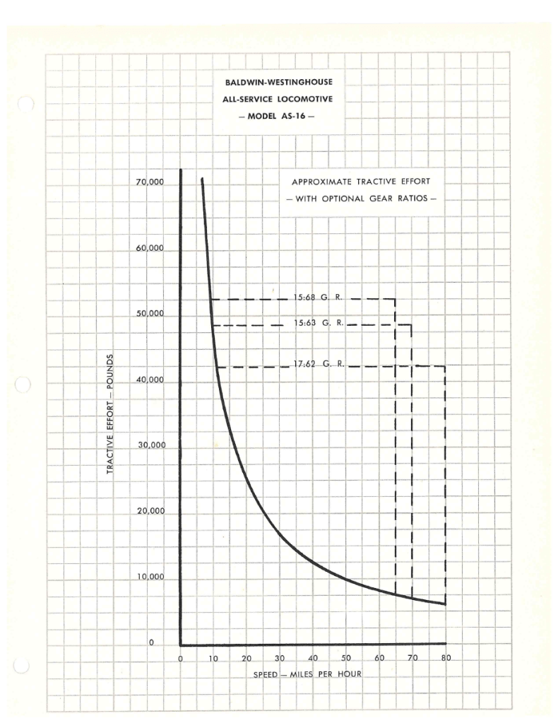
Fig 8 – AS616 approximate tractive effort
Prominently visible at 40mph is our unloading corner, and also featured is Baldwin’s cheaty way of preserving high speed acceleration. Rather than making transition, the optional system would completely short two motor fields – one motor per parallel branch – lowering the resistance in the whole system (and neutralizing all the back emf contributed from those two motors) and, therefore, acting like another step of field shunting beyond what the motors could normally handle. We can also see that the B dashed line is significantly closer to full horsepower utilization (Though a corner can still be seen, this can potentially be attributed to the remaining armature resistance on the idled motors).
Thus we can see – the AS-16 chart is not simplified. An identical, corner-less curve is visible on the RF-16 chart; no other four motor with 370s was offered by 1952. Evidently the available maximum voltage and internal properties of the 370 made transition genuinely unnecessary on Baldwin four axle road-capable locomotives.
Thanks to Nathaniel for putting together this post. All material above was provided by the author. Any questions/comments please drop us a line and we will pass them along!