After the great rush of railroads converting to diesel power in the early 1950’s, the Electro-Motive marketing department had an epiphany. Now that the railroad market had pretty much hit saturation, locomotive sales were starting to slide. A new market had to be found. While the majority of marine and stationary engine markets were being held by sister company Cleveland Diesel, the Electro-Motive Division had their own department that handled the same sales. The PMI department, or Power, Marine & Industrial handled the non-railroad applications of EMD’s engines and equipment. The majority of what PMI was doing at the time was supplying Cleveland Diesel with engines, who in turn would convert them to the specific application. Somebody in PMI apparently had the thought of “Why don’t we start doing this ourselves?” Instead of acting as just a supplier, like what Cleveland Diesel did, EMD would actually build and market a complete product.
In 1954, Electro-Mobile Power was born. A catchy name that described a new concept: Mobile Power Generation. EMD would take one of their engines and generators, and package it in a mobile platform, be it a highway trailer or railcar. The heart of the Electro-Mobile Power trucks/cars would be the new 567C engine introduced the year before, combined with one of the new AC generators. EMD held a press event in the summer of 1954 showcasing the new models: The MH-8, which was the highway trailer version, as well as the M-16, which was the railcar version. We are going to focus on the MH-8 for this post.

The new logo used by Electro-Mobile Power (right) was a sort of caricature of a powerplant: An engine with stack, a generator with sinusoidal wave inside of it representing AC power, and the whole thing surrounded by a “box”.
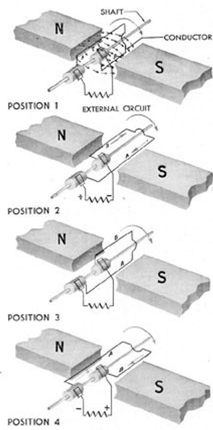
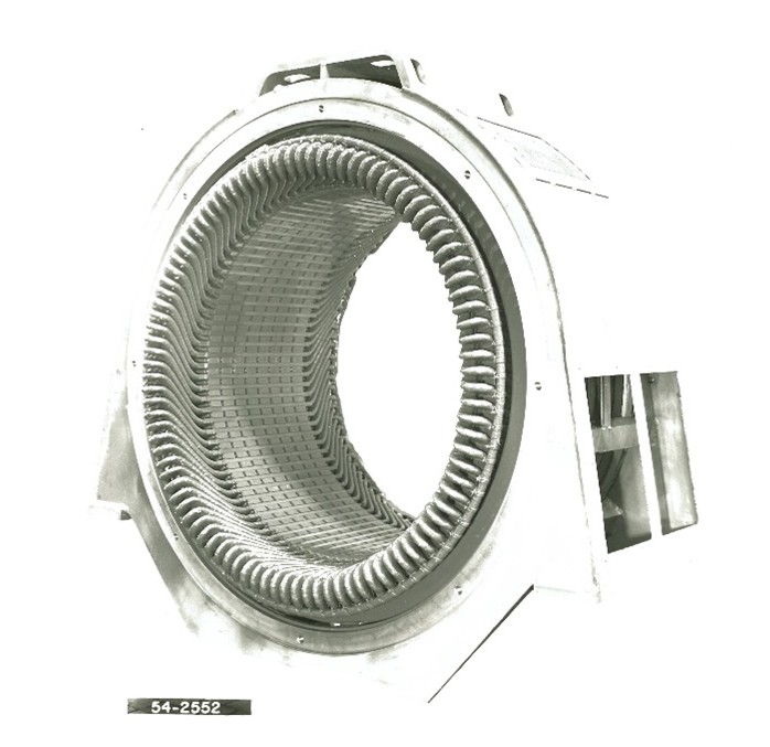
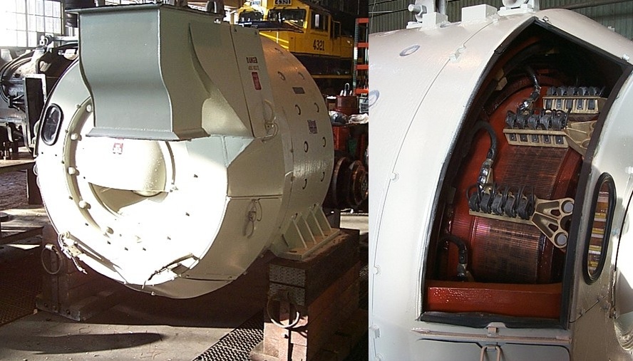
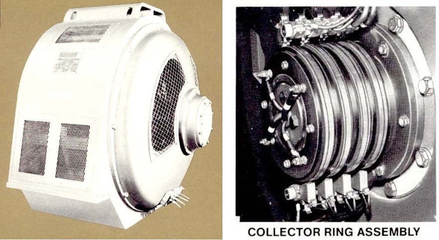
A few months ago, I asked Jay Boggess do a writeup on the introduction of EMD’s AC power Generation, be sure to read this for a full history on how EMD designed their AC generators:
https://vintagedieseldesign.com/2025/02/09/ac-generators-an-introduction-to-the-common-converter-of-mechanical-to-electrical-power/

A well known press photo of the time, EMD held an event in LaGrange showcasing the new Electro-Mobile Power line, including two M-16 rail mounted power cars, and an MH-8 highway trailer. All of the equipment was painted in EMD Demonstrator Blue, with a white lightening stripe. EMD Photo, VDD Collection. Click for larger.
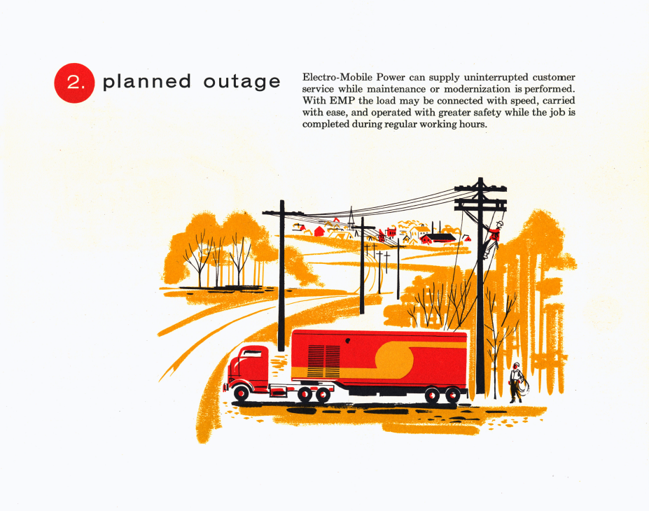
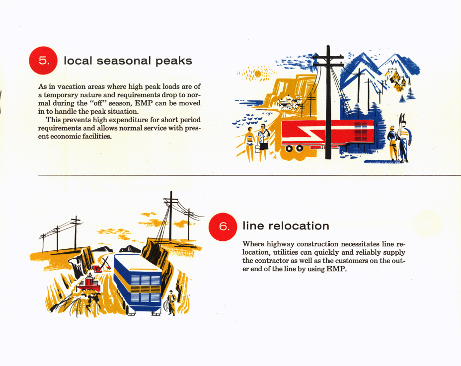
Marketing for the MH-8 was mainly geared towards public utilities. Rated at 500kW, the trailer would be a good “stand in” generator for electric companies doing planned outage type of work such as pole and line replacement. A second market was as an emergency generator. The US Navy would be the largest buyer of MH-8’s for use as backup generators in Navy hospitals. A third, rather unorthodox market popped up: generating power for electric mining shovels in various open pit mines.


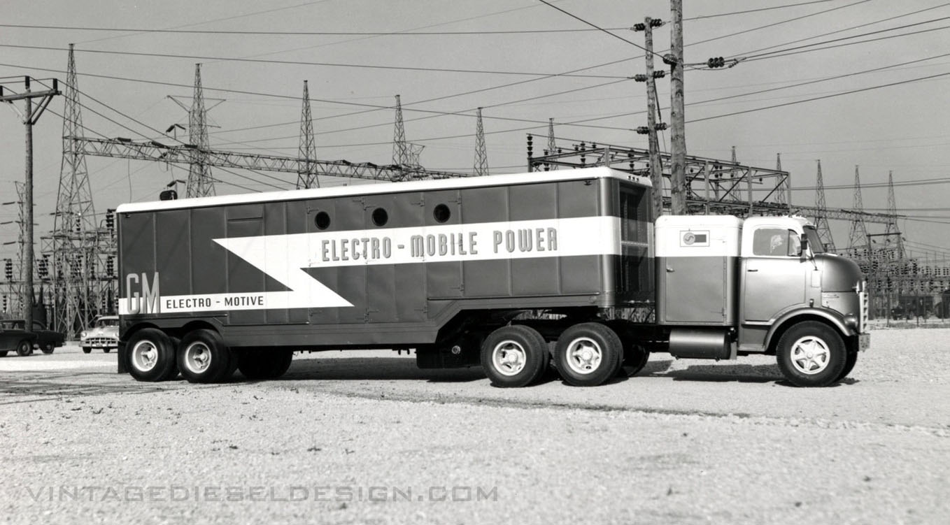
Not only did they build the trailer, through subsidiary General Motors Truck & Coach Company, a GMC Cannonball COE (Cab Over Engine) truck was supplied to pull the demonstrator trailer. Note how much larger the trailer is over the truck. EMD Photos, VDD Collection. Click for larger.
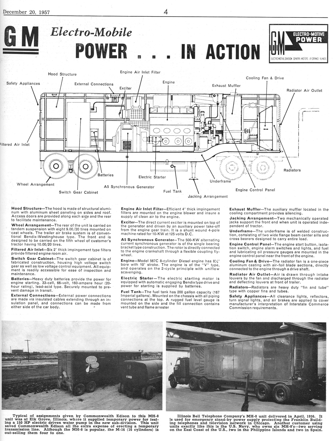
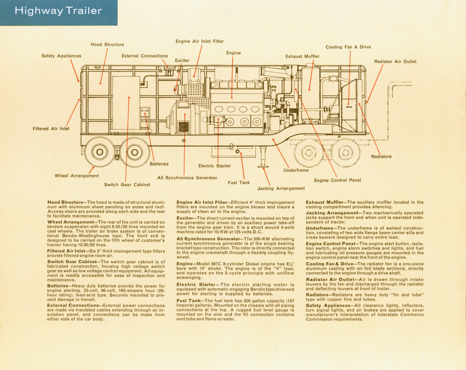
The MH-8 looks like an ordinary highway trailer, however there was no space for cargo inside! An 8-cylinder 567C sat inside the middle of the trailer, which in turn was connected to a 500kW model A5 alternating current generator. The rear of the trailer featured a basic set of switchgear (also built by EMD) with a 50,000kva oil type circuit breaker and dry transformers. The front of the trailer held a muffler (the muffler was on top on the demonstrator trailer), as well as the cooling system. An optional automatic starting system was offered, so the unit could be left on its own to start up when an outage is sensed. Start up to full load could be reached in under a minute.
The 32’11” trailer itself is a heavy-duty design, unfortunately it is unknown if it was built by EMD or subcontracted out. A basic metal box enclosed the trailer to keep it weather tight, with small, hinged doors on the top for the power connections on each side. The main entrance to the trailer was in the rear through a single door, with larger folding maintenance doors on each side. The original demonstrator trailer featured smooth sides, with the radiator intake screen on the top. Production trailers had the screens moved to the side, with either a large set of 4 open grills, or 9 smaller louvers like those used on a locomotive. A smaller 350kW trailer was planned (using a 6-cylinder engine) but was never produced. A truck could have been part of the package as well, using a GMC Cannonball COE – We know that Illinois Bell’s trailer included one of these trucks, however it is unknown if anyone else received the truck too.


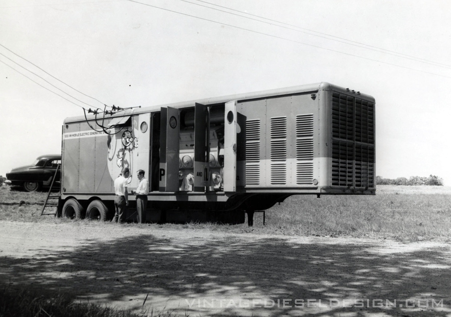
A look inside the trailer shows the basic switchgear, A5 generator, 567C engine and the radiator compartment at front. Production trailers shifted the engine back slightly, and a larger muffler was installed in front of the engine. EMD Photo, VDD Collection. Click for larger.

Production of the MH-8 trailer ran from August of 1955- October of 1960. The MH-8 sales never really materialized in any number. Unfortunately, only 23 MH-8 trailers were built in this timespan. 500kW was really not a lot of power, with communities getting larger and larger, and the same amount of power being offered in smaller packages.
Production List
1 – US Navy Hospitals, 8/1955, S/N 120
2 – US Navy Hospitals, 8/1955, S/N 121
3 – Commonwealth Edison Co., Maywood, IL, 12/1955, S/N 150
4 – The Anaconda Company, 12/1955, S/N 154
5 – Wisconsin Power & Light Co., 12/1955, S/N 158
6 – Illinois Bell Telephone Co., 4/1956, S/N 168 – Used an Elliot generator in place of EMD A5
7 – US Navy Hospitals, 10/1956, S/N 196
8 – US Navy Hospitals, 10/1956, S/N 197
9 – US Navy Hospitals, 10/1956, S/N 198
10 – US Navy Hospitals, 10/1956, S/N 250
11 – Central Illinois Public Service Co. , 12/1956, S/N 199**
12 – The Anaconda Company, 1/1957, S/N 280**
13 – A.G. Schoonmaker Co., 2/1957, S/N 281**
14 – Isbell Construction Co., 2/1957, S/N 291**
15 – Homesake Mining Co. – New Mexico Partners, 5/1957, S/N 292**
16 – Missouri Power & Light Co., 9/1957, S/N 327**
17 – Homesake Mining Co. – Sapin Mining Co., 10/1957, S/N 388*
18 – Homesake Mining Co. – Sapin Mining Co., 10/1957, S/N 389*
19 – Compania Electrica Habana Del Este, Cuba, 3/1958, S/N 410**
20 – Compania Electrica Habana Del Este, Cuba, 4/1958, S/N 328
21 – Stearns-Roger Mfg. Co. (Rare Metals, Inc.), 5/1958, S/N 417*
22 – British Guiana Government, 11/1959, S/N 454
23 – Public Service Co. of Oklahoma, 10/1960, S/N unkw**
Engines with a * used 8-567CDF dual fuel engines.
Engines with a ** used 8-567CR engines

EMD Photo, VDD Collection. Click for larger.

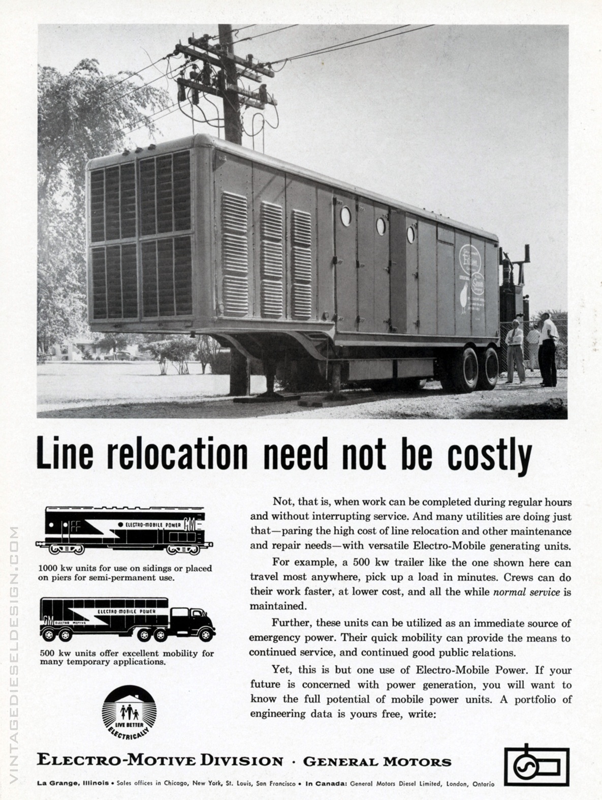
1957 EMD Advertisement, VDD Collection. Click for larger.

1958 EMD Advertisement, VDD Collection. Click for larger. 1955 EMD Advertisement, VDD Collection. Click for larger.

1955 EMD Advertisement, VDD Collection. Click for larger.
As seen in the advertisement above, Commonwealth Edison of Illinois purchased their MH-8 in 1955. The unit featured the louvered side air intakes. EMD Photo, VDD Collection. Click for larger.
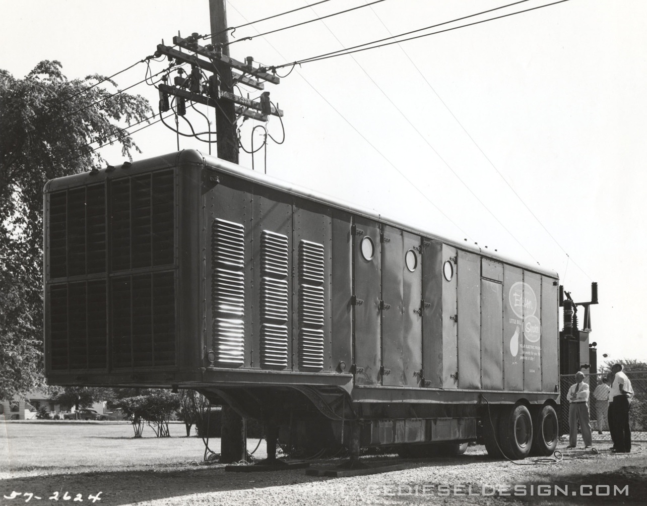
Wisconsin Power & Light Company purchased their MH-8 right after Commonwealth Edison in December, 1955. Note the cables entering into the small hatch on the side just above the gentleman standing. EMD Photo, VDD Collection. Click for larger.

The same trailer has been moved onto another location in rural Wisconsin. The selling point of the MH-8 was that they could be moved to any substation or line by truck, at any time. EMD Photo, VDD Collection. Click for larger.
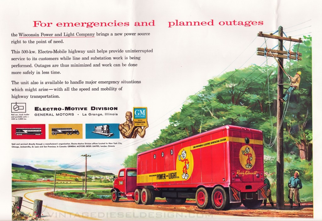
A fantastic 1956 two-page EMD advertisement shows us that the WP&L Co. MH-8 was painted in a splendid red and yellow scheme, with electrical mascot Reddy Kilowatt on the side. 1956 EMD Advertisement, VDD Collection. Click for larger.

EMD put out this basic brochure (below) on the MH-8, with a painting of the production version of the trailer (note the side grills) in demonstrator colors spread out across the front and back covers. Click for larger.


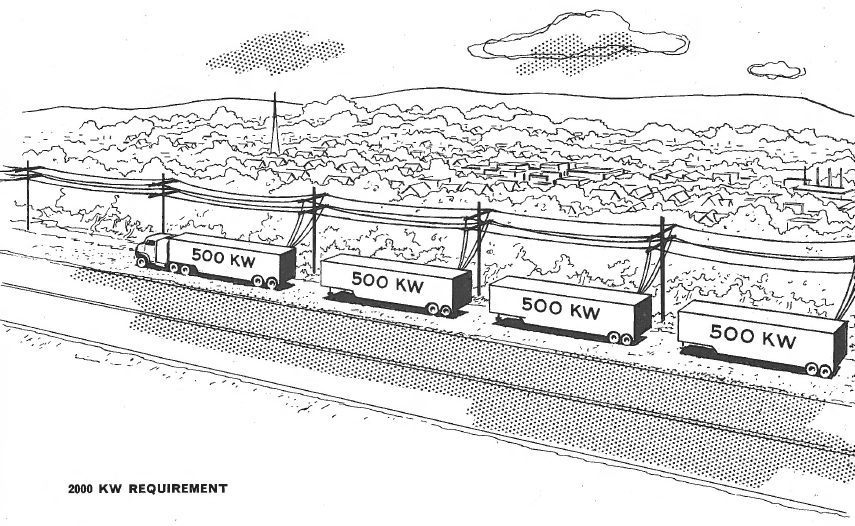
One of the benefits of the MH-8 highway trailer is that there was no limit to how many could be used. Need 500kW? One trailer. Need 1000kW? Two trailers, and so on. EMD Drawing, Jay Boggess Collection.

Amazingly enough – There is an MH-8 survivor! Jay Boggess was able to arrange a visit to its storage location to snap some photos. This trailer is S/N 199, built for the Central Illinois Public Service Company in 1956. All of the following photos were taken by Jay. The trailer has since moved into private ownership, and moved to a new location. As far as I know – this is the only known surviving EMD MH-8.

EMD used these large, stainless steel builders plates on the non-railroad items.

Access to the MH-8 is through a basic door in the rear of the trailer. Unfortunately, Jay was not able to obtain any interior photos.
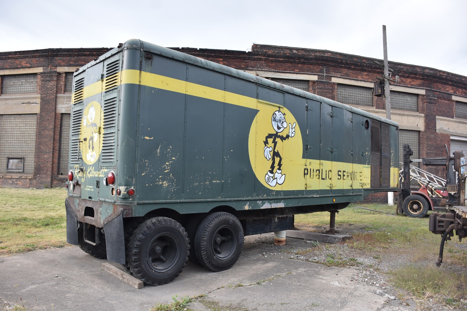

The large radiator intake screens on the side of the trailer. Compare these to the louvers on the ones in the EMD photos above.

The MH-8 had two underslung fuel tanks under the frame, unfortunately one of them is missing on this MH-8.
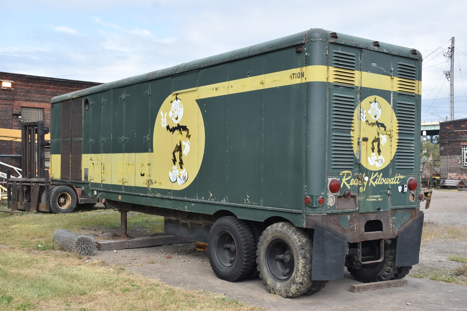
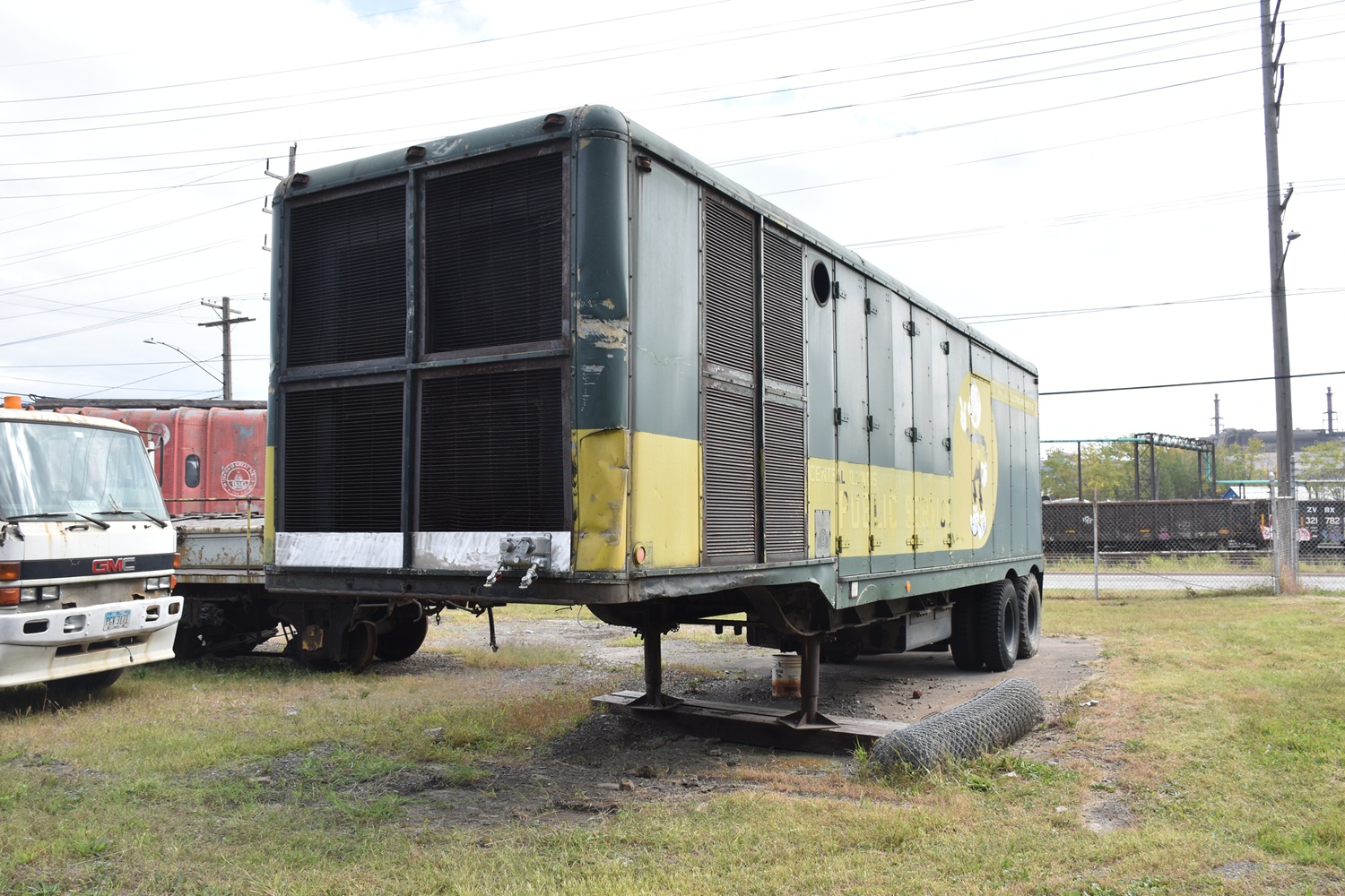
The radiator discharge at the front of the trailer. Its great to see one of these trailers survive, a very rare piece of Electro-Motive history.
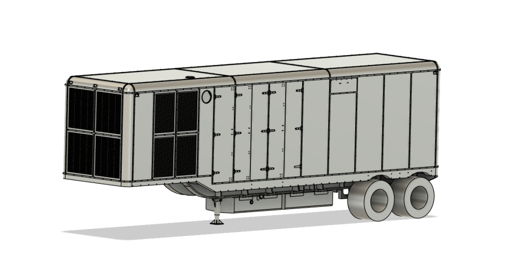
I have been slowly working on drawing the MH-8 in CAD to offer them as a 1/87th Scale kit.
A future installment will cover the M-16 Mobile Power Generating Car, as well as a deeper dive into EMD’s PMI department and such things as the MU Peaking Power Plant’s, Drill Rig’s and other Stationary uses. If anyone has anything to add (or knows of any more survivors) please let me know!