Comparing the 278A to the 567B Internally

One thing I am often asked by railroad friends when discussing the Cleveland 278A, is “Just what is the difference between an EMD 567, and what parts crossover?” Well, its a simple answer, They are two very different animals, and have zero parts crossover. I figured I would throw this gallery together of doing a full gasket renewal on a 278A, which shows the differences, at least in the cylinder and head area of the engine. Something to keep in mind – the 201A was the father of both this engine, as well as the EMD 567. EMD (EMC) engineers went off and designed the 567 from the mistakes of the 201A with the goals of a railroad engine, and Winton went off and designed the 248 which was the marine service engine, which evolved quickly into the 278/278A as I have mentioned in past articles.

The 278A is best compared to the EMD 567B, in that it uses a water deck style liner. The 278A uses an individual water deck area specific to each cylinder, not one section of the block per say, both of which are sealed with O rings, which cause leaks. Leaks are bad, especially when water gets into the oil side of things. Lets dive into a 278A and go through the process of finding a leak, and how to fix it, and compare the engines along the way. Click on all of the below images for larger versions.

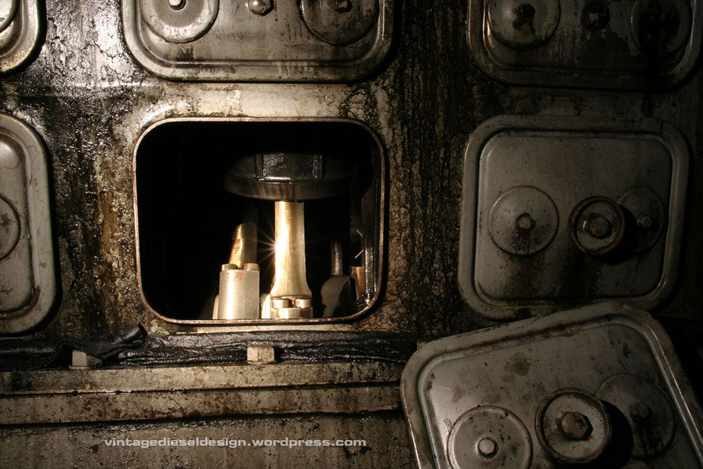
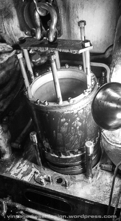
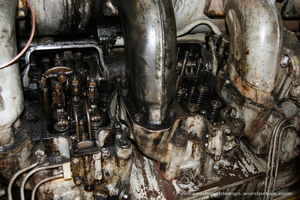
The first sign of trouble, is generally when you see water coming out of the airbox drains. This at least narrows it down to one side, so then you start by pulling all of the covers off, and looking for Niagara Falls.

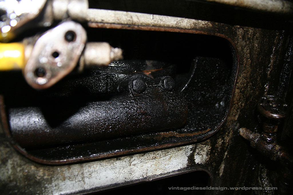
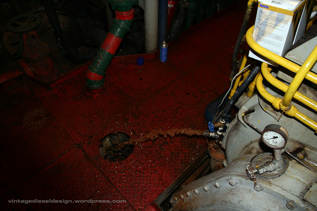
The leak itself can come from two very different issues – The liner O rings are leaking, as seen in this image. Follow the brown trail of water from the bottom of the airbox, leading up to the liner. A second way of spotting the trouble, is when blowing down the engine, you will get water vapor (or solid streams) coming out of the blow down. This is a second area that leaks, the O rings between the head and the liner. When this happens, water will run down into the liner, and out the intake ports in the liner into the airbox – if the piston is down. This will also cause the expansion tank/water side of the engine to pressurize. More on this shortly. A cracked head can cause this same issue, which can be a bit more troublesome to pin point, especially if it only does it when they are warm.

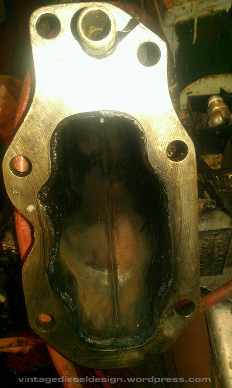
A third source of water issues on a Cleveland can be in the exhaust elbows. EMD’s have an integral exhaust path, whereas the Cleveland’s have individual exhaust jumpers between the head and the manifold which are all water jacketed. Look closely and you will see pitting in the elbow, causing water to leak into the head and liner through the exhaust valves.

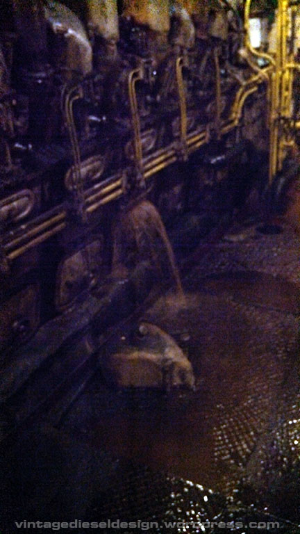
The fourth area of concern, and this is NOT Cleveland specific – is when a liner lets go. In this case, the engine was not blown down before startup, and the liner violently let go (it is a sound I will never forget). The side of the liner pushed out, thus the entire water system dumped out in a hurry into the airbox, once again, Niagara Falls resulted. Now, Cleveland’s have a pressure relief valve on each head, thus when this happened, the valve opened (and shot a solid stream of water out) preventing the connecting rod from bending. EMD’s don’t have this. The only damage from this was the piston rings were broken by the chunk of liner that failed. And on that note – If your running an old engine, take the 5 extra minutes and BLOW IT DOWN every time! It can save you some serious trouble!

Now, we drain the engine down..

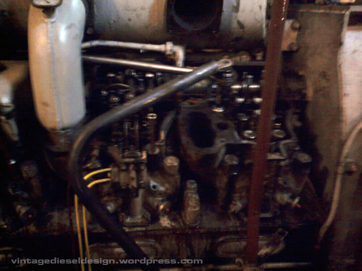
…and start to take it apart. Fuel and overspeed lines are removed, rocker assembly removed, exhaust jumper removed. In this case we pulled the injector also, but it is not required.

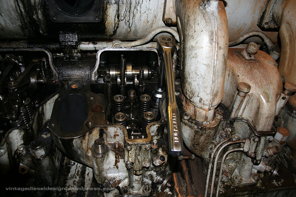
Sometimes it takes some creativity to get all the tools in there in certain spots on these engines. In this case a chunk pf bent pipe from a handrail was used as a cheater bar. Hey, it worked! 4 nuts hold down the head to the block, and 6 bolts hold the head to the liner. EMD’s the head sits inside the block, but the Cleveland’s sit on top of the block, and do not use shared crab nuts.

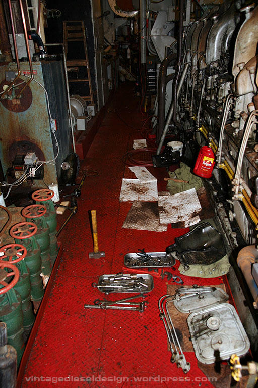
No difference between them here – Lots of rags, and piles of parts!

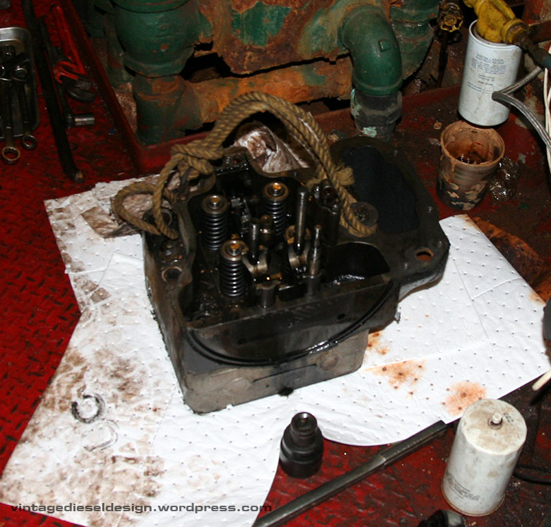
With the head removed, we see one of the biggest downfalls of the 278A. There is a half moon shaped groove that fits a round rubber seal. When these seals start to go, the engines leak oil, and badly. In the 1950’s, the US Navy devised a tool and a process to push the head back onto this seal before you torque them down. This helps, but not that much. This, is why almost every Cleveland is covered in oil. The valve cover gasket seals (two per cover) are not any better, and are very temperamental. EMD built a box around their oil leaks…

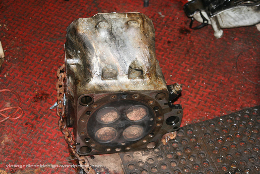
Bottom of the head. Nothing special here. The left is toward the center of the engine. The large hole to the right is where the injector control rods goes into the head.

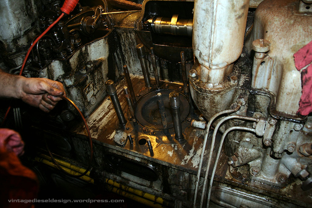
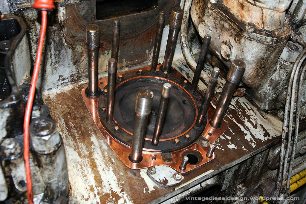
Now we have the head off. Pulling the head is typically the hardest part of the operation, as the stud holes will fill with oil and sludge, as well as carbon – more on that one shortly. Cleveland’s use direct air start, meaning no starter motor. 300PSI (up to 600 was used on the Sub’s) is directly admitted to the head in order of timing in 8 of the heads – that’s what the small line is just above the right most, lower head stud.

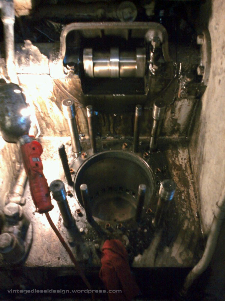
With the head off, we are at a crossroads. If the liner O rings are leaking, you need to forge ahead and pull the liner. If you are getting water through the liner, and the expansion tank is bubbling off – that means you lost a fire ring, which is a solid copper ring that seals between the head and the liner. When this fails, it burns out any number of the 12 small rubber O rings that seal the water side of the head and liner on small copper ferules. We dubbed these the little rubber douchebags. If the liner is still sealing good, you don’t HAVE to pull it, but it is typically good practice to just replace them all while its apart.

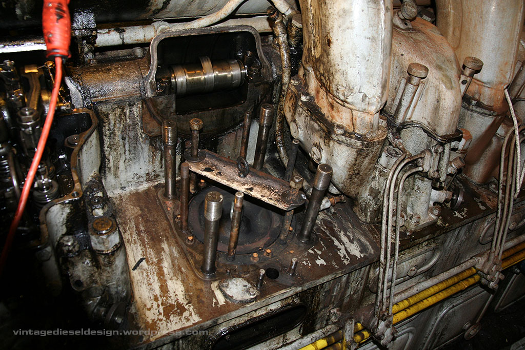
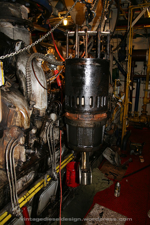
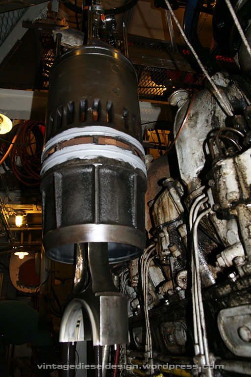
To pull the liner, you need a liner lifting plate (we had to make one, we now have an OEM one..). The piston crown has a small tapped hole for an eyebolt, thus you can secure the piston to the plate, and lift them out as one assembly.

But first, you need to pull off the bearing shell from the connecting rod. Cleveland’s use an individual rod and bearing for each cylinder, EMD’s double up with their fork and blade style assembly.

In this one, we pulled the piston out as the rings needed to be changed. 278A’s use a traditional wrist pin assembly, whereas by the later 567A engines, EMD switched to the floating piston.

Pulling the liner out – Cleveland’s have two liners available, a cast style, and a later fabricated style, which are interchangeable. The two ferrules that are closer together are the markers telling you this is the outer edge of the liner.

Liner and piston/rod is out. The rusty area is the where the water enters the liner.

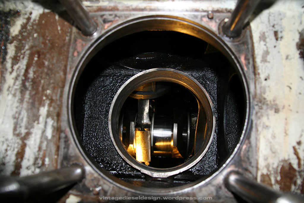
Looking down through the airbox, you can see the water deck area. Water enters through the water manifold that runs through the airbox into the liner. The EMD 567C and Cleveland 498 engine simply used a bolted on extension from the manifold pipe directly to the liner, eliminating these O rings. These O ring seats can actually be changed, but it is an enormous project. You can see here how Cleveland’s have individual connecting rods on each connecting rod journal.

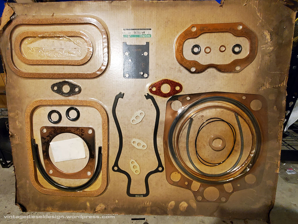
A full gasket kit for a Cleveland, which encompasses all new O rings for numerous things, cork seals for the covers, exhaust jumper gaskets and many other small gaskets.

With the O ring grooves cleaned up, the new O rings are installed and set in a bead of silicone, which helps seal them, as well as keeping them from pulling out when installing the liner back into the block. The liner is lubricated with dish soap to help it slide in.

With the liner back in, a new copper head gasket is installed, new fire ring, and new O rings for the water jumpers and oil seals on the rear of the head. A large cork circular gasket seals the injector control rod hole and the head. EMD’s essentially have all of this combined onto one gasket. Note that the liner is not fully seated down – This will be remedied when the liner is bolted to the head, and it is all cinched down.

With the head back on, everything else goes back together fairly quickly. The head is bolted to the liner with 6 bolts, which are torqued to 175 ft lbs, (290 on the 567B), and the 4 bolts holding the head get torqued down to 650 ft lbs (1800 on the 567B). The exhaust elbow uses two copper clad gaskets, as well as two smaller gaskets for sealing the water side (Cleveland’s are water cooled exhaust). It is a bit tricky to put them on, as the lower bolts are fine thread, and the upper bolts are coarse thread, so you cant mix the bolts up. You essentially have to roll the jumper on, starting with tightening the lower bolts first, in order to compress the gaskets, and line the top up.

Hopefully this answers some more of the mechanical questions of how the 567 and 278 engines compare internally. Down the road I may do something a bit more detailed on this and cover the other portions of the engine, and how they are different, such as the blower, oil and governing systems. Something to note about the Cleveland’s – they require no special tools to take them apart, outside of a torque multiplier.

Tug Profiles – M. Moran

A few months back, I made a post on the tug Luna and Venus, of the Boston Towboat Company, dubbed Historic Tugs I. The intention was to highlight museum vessels and whatnot with historic documentation and photos. To change that a bit, I am going to start a new series covering just tugs of the 1930’s-1970’s, including both new and repowered boats, using several styles of propulsion. This first tug profiled, will be the M. Moran.

Not much has to be said about Moran Towing, one of the oldest and well known tugboat companies in the world, founded in 1860 by Irish immigrant, Michael Moran. Moran Towing is a well established company, using a vast fleet of tugs, ranging from small 80′ direct reversing Canal tugs, to large, WWII surplus ocean going 165′ tugs, many of which were on charter from the US Navy. Fast forward to 1960: These were all single screw tugs, never exceeding much more then about 2000HP. Moran Towing had a long history of working with TAMS Inc., and later the General Motors Marine Design Section under naval architects Richard Cook and later Joe Hack.

In the era, just about every tug was considered “Ocean Going” (a scary thought..), however in reality only the larger, WWII era tugs really were just that, with the rest being glorified harbor and coastal tugs. Joe Hack would design Moran a 120′ tug, with a 31′ beam, and an 18’9″ depth. A new first for Moran was also introduced – twin screw propulsion.

Click for larger – CDED Drawing, collection of VDD

The tug was named the M. Moran, after the founder of Moran Towing’s Michael Moran. She would be the 7th tug named for him. The M. Moran was designed for an 11,000 mile range, or anywhere in the world – holding a capacity of 75,000 gallons of fuel. The M. Moran was built in Texas, by Gulfport Shipbuilding.

Click for larger – CDED Drawing, collection of VDD. I acquired these original drawings several years ago, they are several feet long! Thanks to Jay for scanning them.

The M. Moran had a rather unorthodox layout, using two split levels underneath the wheelhouse, giving her a rather odd, low profile appearance, but affording a massive amount of interior space. 9 full staterooms, two of which were dubbed a radio room, and a sick bay. A large central galley was located over the engine room – thus she lacked any actual upper engine room, also known as a fiddley. Behind the galley was a space for a 75HP Almon-Johnson towing machine.

Diesel Times – Collection of J. Boggess

You guessed it – the M. Moran was Diesel-Electric, powered by a pair of Cleveland Diesel, 1750HP 16-278A engines, with Allis-Chalmers main generators – all WWII surplus equipment, giving her a rating of 3,500HP. The engines were factory rebuilt, and were originally installed in US Navy Landing Ship LSM-529 (engine #55810), and LSM-324 (engine #55284). Ironically the other engine from LSM-324 would also go to Moran, re-powering the steam tug Michael Moran. The tug had a pair of Detroit Diesel 6-71’s for generators, as well as a piggyback shaft generator belt driven on top of each main generator. The tug had a pair of 9′ 10″ wheels, and a rated bollard pull of 95,000lbs.

Diesel Times – Collection of J. Boggess

The wheelhouse of the M. Moran featured American Engineering electric-hydraulic steering system, and the same Lakeshore throttle stands used by Cleveland for a number of years, of course modified for twin screw. A Sperry gyro, and radar rounded out the interior – pretty spartan, even for its time. While the maneuverability of Diesel-Electric is well known, an interesting feature of the M. Moran – being twin screw, was the cross-compatibility. The tug could run on only one engine, and power both propulsion motors when running around lite tug, somewhat of a throwback to the Destroyer-Escorts of WWII (where the propulsion motors in the tug originated), where various combinations of engines could power certain groups of motors.

Diesel Times, 10/1961 – Collection of J. Boggess

The M. Moran was placed in service on 9/27/1961, and her very first trip, just a week later – would take her all the way to Pusan, South Korea, towing the 30,000kW generating barge Resistance, a WWII LST converted into a powerplant. The M. Moran was well covered in Cleveland Diesel’s Diesel Times newsletter Diesel Times, as well as several issues of Moran Towing’s own newsletter, Tow Line.

Moran Towing Publicity Photo
Robert Lewis Collection

By the late 1960’s the M. Moran would gain a large upper wheelhouse. She would spend many years running around the Gulf area towing large project cargo, as well as the occasional foreign tow. The M. Moran was briefly renamed as the Port Arthur for a brief time in the early 1970’s, likely operating under a charter.

Robert Lewis Collection

Moran would go on to order a 2nd tug, to the same design as the M. Moran, named the Esther Moran. The Esther would be built in New York, by Jakobson Shipbuilding. At the same time, Jakobson also built the Patricia and Kerry Moran, which used the same hull design, however it was shortened 12′ with the tug being setup for harbor work, thus lacking the towing machine and split levels. These three tugs would be the last new tugs powered by Cleveland 278A engines. Cleveland was rolled into Electro-Motive in late 1961.

Robert Lewis Collection

Both the M. Moran and the Esther were not Cleveland powered very long. Both tugs would be repowered with EMD 16-645E engines with air clutches by the end of the 1960’s, giving them a new rating of 6,300HP – a massive amount of power at the time. Joe Hack would revisit the split level design with a pair of tugs for Gulfcoast Transit, the Katherine Clewis and Sarah Hays.

Will Van Dorp Photo

In 2000, Moran sold both the M. Moran and Esther Moran to Canada’s McKeil Marine. The M. Moran became the Salvager, and the Esther as the Salvor. The Salvager became the Wilfred Seymour in 2004, later being shortened to Wilf Seymour. Both tugs operate in the Great Lakes, and both would be converted into Articulated Tug-Barge combinations, with the Wilf getting a Bludworth coupler, and the Salvor a JAK system. The Salvor was laid up in 2018, and the Wilf is still in service. 10/2021 update: McKeil has scrapped the Salvor in Hamilton, Ontario.

Will Van Dorp Photo
Painting by Carl G. Evers

Noted maritime artist Carl G. Evers would do several paintings of the M. Moran, including one of her in Korea. Several of Carl’s paintings have graced the cover of Moran’s Tow Line.

More on the M. Moran and Esther Moran:
https://tugboatinformation.com/tug.cfm?id=772
https://tugboatinformation.com/tug.cfm?id=746
https://gltugs.wordpress.com/wilf-seymour/
https://gltugs.wordpress.com/salvor/

Note – Yes, I know the caption text is not centered under each photo. It is a glitch in WordPress that I have yet to figure out..

Winton & Cleveland Diesel: The List.

Over the last few months, I have been combing through the records for Winton, and later Cleveland Diesel, and put together the following master list of every engine produced by them. This is the result of several nights of going through 2000+ pages of entries, and then spending the following several months filling in the gaps with specifications using various manuals, brochures, company newsletters and everything else, and even still, there are many, many holes with the early engines.

The records start with engine #15 – thus I can not fill in those very first engines. Note that Winton assigned model numbers to several of their auxiliary units such as compressors and pumps, and are labeled as such below.

3-2023: Since making this post in 2020, I have been able to fill in a huge amount of holes in this, as well as acquiring an official Cleveland listing. This will be posted in the next few weeks.

Click for larger

The last Winton engine before being purchased by GM was engine number #3559 on 6/12/1930, a model 148 engine for Electro-Motive. Winton was purchased by General Motors on 6/20/1930.

Click for larger

On 12/30/1937, Winton Engine Corp., was renamed to the Cleveland Diesel Engine Division of General Motors. The Final Winton Engine was #5359, A 12-201A for Railroad Service.
Note 1: 4432/3 are the prototype 201 engines, listed as “used 201” in records.

Click for larger

When it comes to horsepower ratings, especially on the later engines (278A, 268A, 567C), there were simply too many horsepower numbers to list, as it varied by application.

Note that by now – we see engines that are made by sister companies including Detroit and EMC/EMD. Early on, the Detroit Diesel engines sold through CDED (typically part of a “package” for a boat) carried both a Detroit Diesel as well as a Cleveland Diesel builders plate. In the case of the Detroit engines, this was dropped by the 1940’s.

However – with the EMC/EMD 567 line, engines sold though CDED for marine and stationary use carried only a Cleveland builders plate well into the late 1950’s. Only the very last few 567 engines sold through CDED carried both an EMD and a CDED builders plate. More information on this can be found on our post documenting Winton/CDED linked below.

Also to note: This list covers only engines built or sold through Winton and Cleveland Diesel. This does NOT cover any additional engines or developments by Detroit Diesel (such as the 51 or 53 series and later) or EMD (184A, 645 etc.)

Thanks to J. Boggess and P. Cook for helping with this. As always, there are numerous holes in the listing, so please send us a message with any additions or corrections.

Cleveland Diesel Engine Division – GM’s war hero turned ugly stepsister.