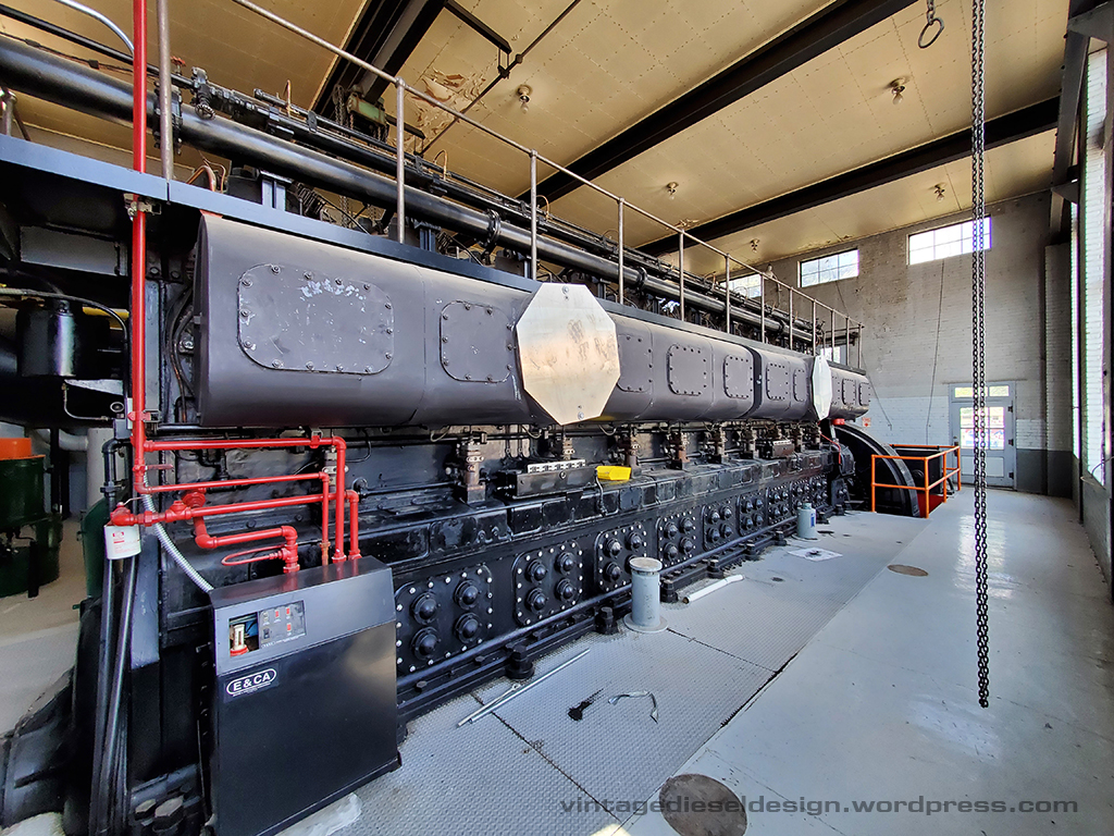
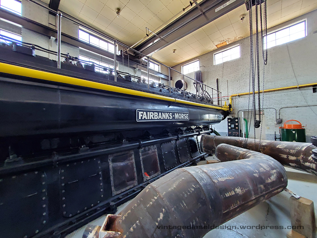
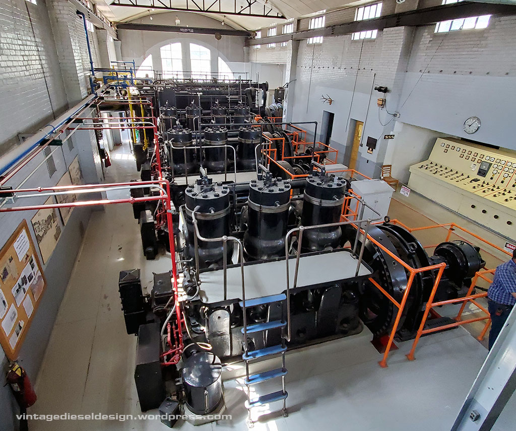
Engine #7 at Delta is a 10 cylinder, 3500HP, Dual Fuel engine. The engine is rated for only 277 RPM, and has an 18″ bore and a 27″ stroke.
Click on all of the photos for a larger version.
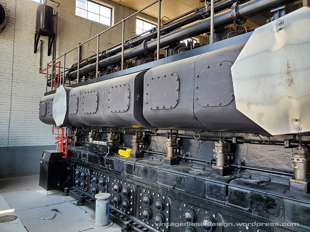
The creative use of old stop signs are covering the exhaust ports, which would turn and enter into the flood in the circular covers.
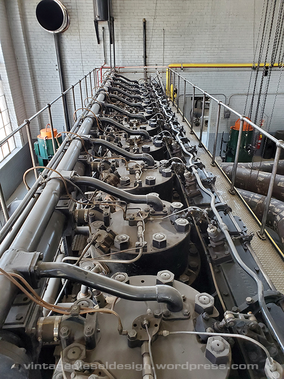
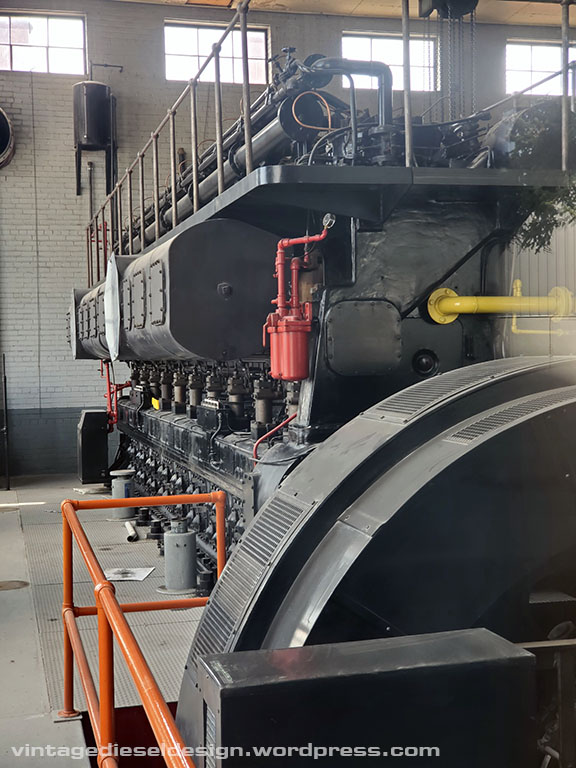
One of the fuel injection pumps. A camshaft in the box underneath drives these, with a copper line out of the top leading to the fuel injection nozzle in the head.
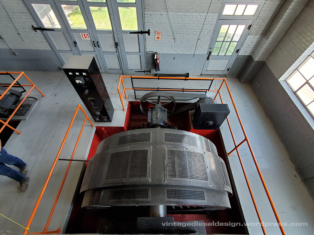
The engine drive a Fairbanks-Morse 2130kW, 2400V AC Alternator. The excitation generator is belt driven off off the end.
Looking down at the top of the cylinder head. The large pipe leading into the top of the head is the incoming Natural Gas supply. Going clockwise, is the gas admission valve driven from the upper camshaft, the air start check valve, with the air supply under it, jacket water exit into the upper water header, above that is the cylinder relief valve. In the center is the fuel injection nozzle. According to the builders plate, this engine is a 31A18 – FM documentation calls the Dual Fuel engine a 31AD18, maybe this engine was converted after installation?
The pipes in the foreground are the previously mentioned exhaust pipes, which were removed for remediation.
Just outside of the engine hall, is a small clean air room. Inside, is the scavenging air blower for the engine (all 10 cylinder engines used an external blower) – a Roots-Connersville 24″ centrifugal blower. The blower, is rated at a whopping 300HP and moves 17,500CFM of air.
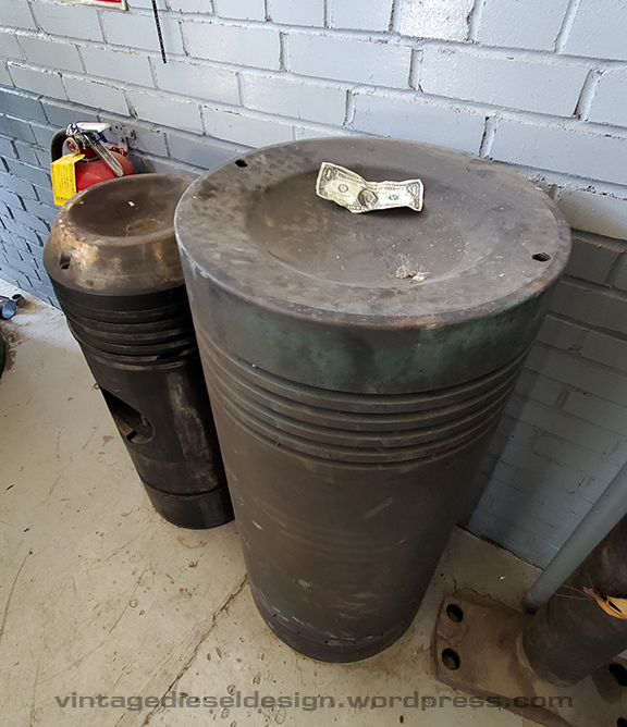
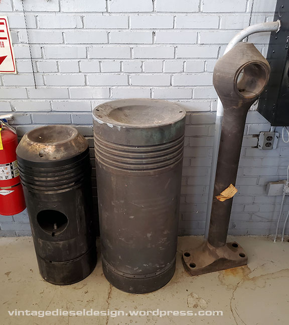
Just how big is an 18″ piston? Here it is with a dollar bill for reference..
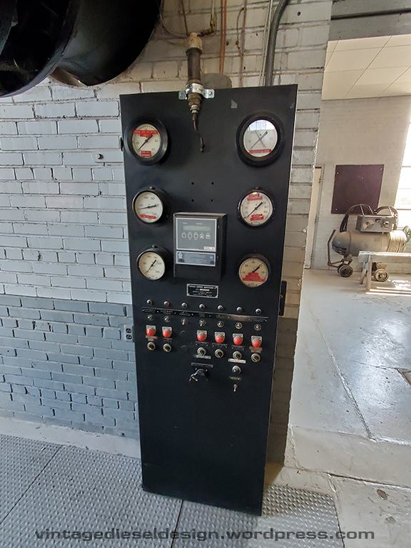
Gauge and alarm panel – Just not as cool as those 1930’s era ones on the 32E engines..
The photos here simply do not do this engine justice, and just how BIG it is!
Lubrication chart for the engine. I would LOVE to add one of these to my collection. Anyone got one they want to sell?
This concludes our tour of the Delta Municipal Light & Power Plant. Thanks again to the guys for the fantastic tour! I can only hope that this plant can be saved, or at least some of the engines. I would love to see the 31A18 saved, but realize that would be one hell of a feat, due to the shear size. That little 4 cylinder 33 would be a neat museum piece as well.. I may make another post down the road with some other random photos in the plant I took.
Next week starts a new series – Historic Boat Profiles, with our first featured boat being the tug M. Moran, Moran Towing’s first twin screw tug.
Continuing on our roadtrip last month, leaving Salt Lake City and heading towards Denver, we were sort of forced to take the scenic route, due to Route 70 being closed for fires – a common theme on this trip.. But hey, scenic roads are always better then highways! And, it lets us do some more exploring on the DRGW Narrow Gauge lines through Cimarron, Gunnison and Monarch. So, dropping down Route 50 out of Grand Junction, we come into the small town of Delta, Colorado. A small construction detour had us routed through downtown, and I had a lightbulb moment..Delta…They have an old Municipal plant full of Fairbanks engines! I remembered an old website from years ago (link on the bottom) with some photos, and doing some digging last year I read the plant was closed and they want to repurpose it… Well hell, lets find it!
Well, that was easy, being that its right on the edge of town, on 50. I had to stop and atleast take a look in the windows. So, I find a place to park next door and walk up to the windows.. and bam, there I am greeted by the plants largest engine, an FM 31A18. So I take a photo through the window.
I walk back to the car past the office, and say what the hell, let me knock on the door. I go to the car and grab my friend with me and tell him “If you want to tour the plant, lets go give it a shot”. Go to the office door, knock knock…I am greeted by a gentleman and ask him if by chance we can take a look around…
“Sure! Come on in! We love showing this place off!” Yep, defiantly not in NYC anymore..
Click for larger
We got the grand tour! Unfortunately, In a streak of laziness, I opted not to grab my real camera out of the car. A decision I regret. I am going to break this post up into several parts by engine, and give a run down of each engines history and specs.
Left is a 14″ FM piston, and the center is an 18″. We will come back to this later.
The Delta plant was built in 1937 with the 32E engines originally, and expanded in the mid 1950’s. Here is the sad part, the plant was shut down for the last time in 2014, and has been idle since. I stumbled on plans from the city last year that they want to repurpose the building unfortunately. This place is a living museum of diesel engines and rural power generation and really deserves to be preserved as it is. Any old engine groups looking for FM’s might want to get in touch with them…
At the time, FM was not only the engine builder, but would act as the contractor for the site, planning the optimal layouts and plan for future expansions.
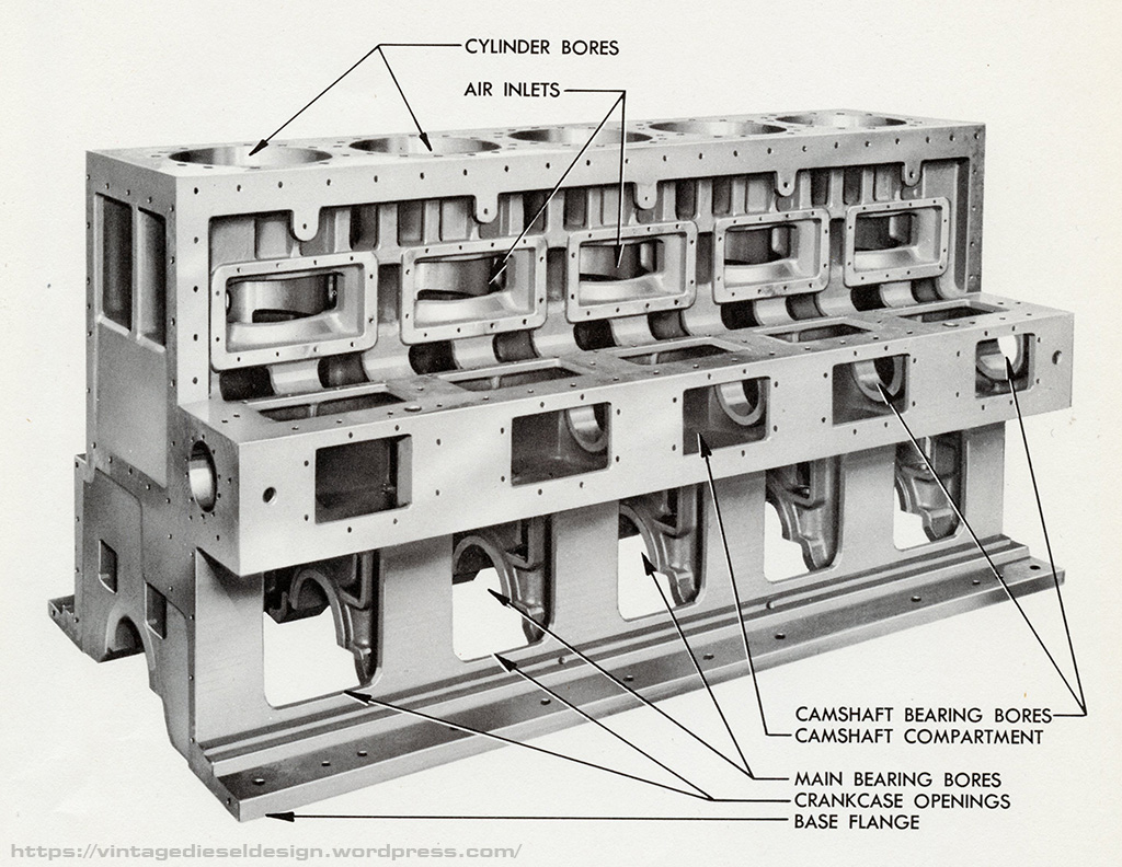
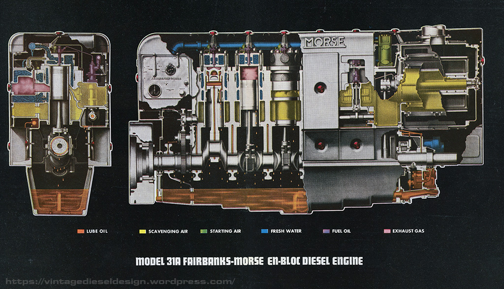
As we outlined in our very first post here, Fairbanks-Morse introduced a line of what they called “En bloc” engines, meaning whole, which to put bluntly, they used a one piece cast crankcase with integrated cam pocket and bearing bores, which F-M advertised as putting all of the pieces in perfect alignment every time. Attached to the block would be the various auxiliary pumps, exhaust belt, water header, blower, etc.
The F-M 31A En bloc engine seems to have made its first appearances in advertising around 1945. This specific line of 31A appears to be the decedent to the 31A “Borneo” engine. The first real production of this 31A series seem to start around 1949, which is the publication dates of each of my manuals. The 31A was offered in 3 bore sizes: 6 ¼”, 8 ½” and 18”.
An 8 Cylinder 31A8 ½“, setup for stationary service – Note the Woodward UG8 governor control panel. FM Photo. Click for Larger
The 31A we will be discussing in this post is specifically the two smaller versions of the model, the 31A6 ¼” and the 31A8 ½“. The engines are two stroke, cross flow scavenged, with an integrated scavenging blower, as well as an optional compressor, bilge pump and water pumps. Both models were offered in a direct reversing marine model, or a stationary model, and in the case of the larger 31A8 ½“, a dual fuel version. An additional option on the direct reversing marine engine, was a reduction gear with an Airflex clutch (note- this is not a reverse reduction gear, the engine is still direct drive). Both models were available in either rotation.
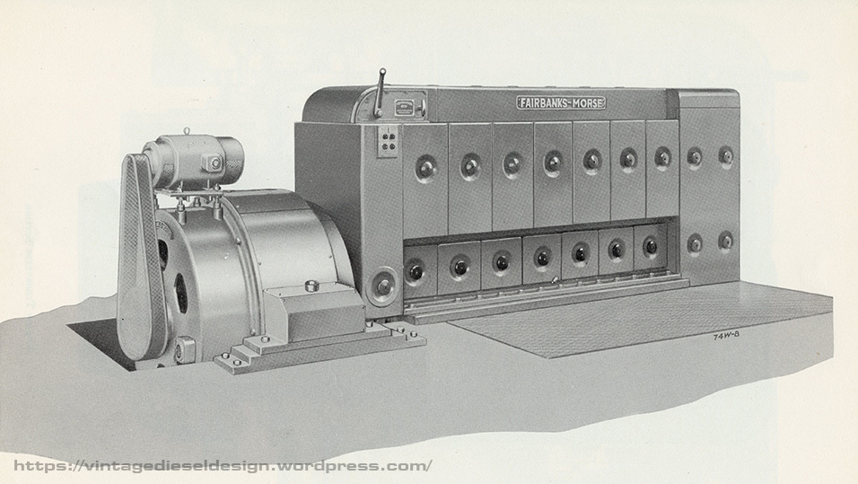
The cool part about the 31A engine line – it was a fully enclosed engine. Removable covers covered the entirety of the engine, front to back, with a very 1930’s Art Deco type look to it. It also looks like a toaster, and this will be the first model we cover in a series of “Engines that look like toasters”.
A 7 cylinder 31A6 ¼” setup for stationary service, driving a small generator. FM Photo – Click for larger.
A 5 Cylinder 31A8 ½“ setup for marine propulsion, with the Airflex clutch and a reduction gear. FM Photo – Click for larger.
While the engine is offered in two sizes, they are virtually identical engines, much like how the F-M 38 series (5 ¼” and 8 1/8” bore) were designed – parts were just “scaled down”. The notable difference being that the smaller 31A6 ¼” used a timing chain for the camshaft drive, while the 31A8 ½“used a gear drive. It seems to be that the larger 31A8 ½“ was much more common then the smaller bore, which seemed to be popular in smaller work boats.
The one piece cast crankcase and cam pocket. FM Photo – Click for larger.
Let’s do a quick walk through of some of the features of the 31A.
Up on top, the 31A used a very basic lump of a cylinder head, like most of the previous F-M engines. A central fuel injection nozzle, along with a start air check valve, and a space for either a test cock or a start cartridge adaptor. The cylinder heads bolt down onto the liners, with a simple copper gasket between the firing surfaces, and rubber rings on the water passages.
31A Cylinder Head. FM Photo – Click for larger.
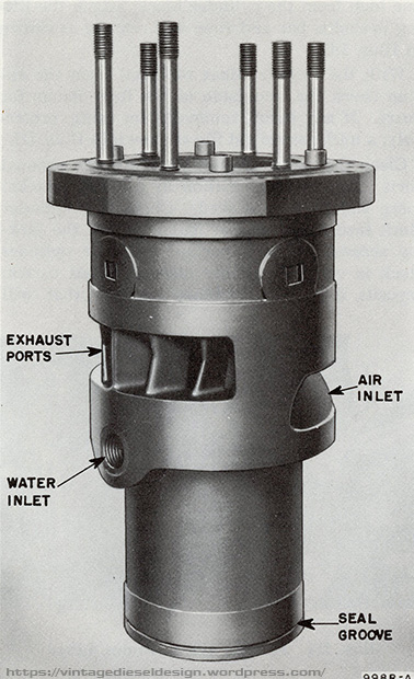
Unlike most previous large F-M engines which the cylinder liner sits on top of the main crankcase, the 31A uses a cylinder liner that inserts into the block. The air inlet ports, and the exhaust ports are surrounded by a water jacket supplied through an unorthodox method. Cooling water enters the engine into the (water jacketed) exhaust manifold. A threaded fitting allows water to exit from the exhaust jacket, into the lower portion of the liner, flowing up through the head into a water header. On the bottom of the liner was a simple O ring to seal the scavenging air from the crankcase.
Note that there is no actual seal between the air and exhaust side of the liner. FM Photo – Click for larger.
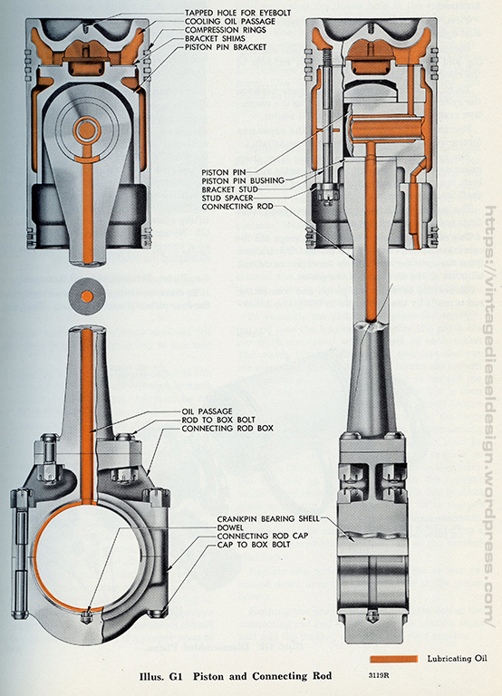
The 31A series engines use only a conventional style full pressure oil system (unlike other models which used a combination of force feed Madison-Kipp lubricators as well as a pressure system), which force feed all of the bearing surfaces, as well as drilled crankshaft which feeds oil to the connecting rods and pistons. The bearing shells for both the upper and lower main bearings, as well as the crankpin bearing shells were all interchangeable.
The 31A piston used a set of bolts to hold the carrier to the piston. On the lower end, like all of the previous large bore FM engines, the crank pin bearings were in their own separate holder, thus when you had to pull a piston, you did not have to detach it from the crankshaft. FM Photo – Click for larger.
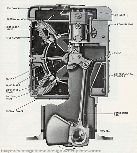
Scavenging air for the 31A series is provided by an attached vane style, oscillating blower. In layman’s terms, it’s a big moving flap. Incoming air comes in through a set of intake valves, gets compressed (1.5-3psi), and exits into the airbox through a set of discharge valves. The moving vane is run off its own connecting rod on the forward end of the engine. Intake air could be routed through the top, or front of the engine. Engines so equipped with a compressor; this was driven off the lever that runs the blower vane.
Oscillating vane style blower, and attached compressor. FM Photo – Click for larger.
Under the hood on the control end, things are a little more complicated. To maintain the streamlined appearance, all the control rods are inside. Follow the diagram – Incoming fuel comes into the fuel header on top of the injection pumps. Each injection pump is driven off the camshaft. The fuel rack on the pumps is controlled by the governor – in this case, a direct reversing marine engine, using a Woodward SG8 governor. Governor speed is controlled by a speed lever. The governor is driven off the camshaft, which also drives the fuel pump, as well as a very basic, mechanical overspeed governor trip system. Engine direction is controlled by a separate lever, which controls an interlock on the air side (to prevent the engine from starting if it is still moving in the opposite direction).
The fuel/control side. FM Photo – Click for Larger.
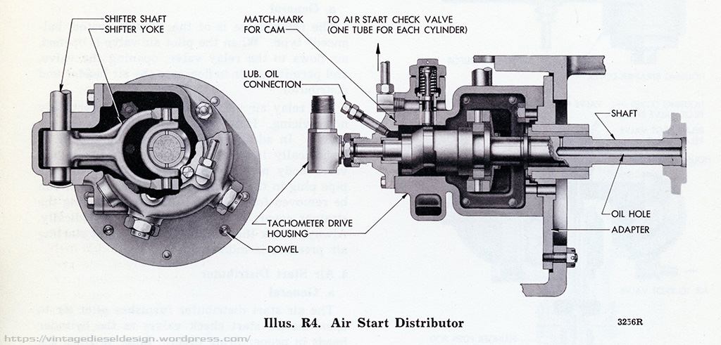
Moving on to the air system: The shift lever controls a rather complex pilot air system. Driven off the camshaft gear drive train, is an air distributor. Think of this like a distributer in a car. Instead of controlling the firing order of spark plugs, it controls the air start sequence timing. Putting the lever to start, air from the pilot valve, opens the air start relay valve, thus filling air header with start air. At the same time, air from the distributor. opens a check valve on the appropriate cylinder, thus letting the start air in. The same lever also has a cam that is tied into the fuel rack and governor, to set the fuel load when either in the start or run position. In order to switch from ahead to astern, the shifter lever also controls a shifter cam, which in turn runs down to a shift fork inside the air start distributor. This shifter moves a small camshaft to choose the appropriate timing for ahead or astern starting.
Control air side of things. FM Photo – Click for Larger.
The rotary distributor valve that controls pilot air for starting in a specific direction. Much simpler then the large sliding camshafts a number of big bore engines used. FM Photo – Click for larger.
Stationary engines still use the same system; however, it is slightly simpler without having the additional moving shifter and gear for the reversable timing. Stationary engines used a Woodward UG8 governor, with a faceplate and knobs for the extra controls.
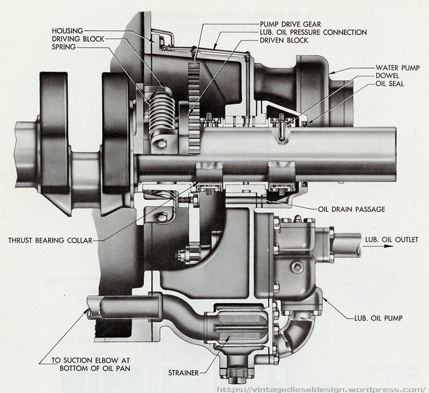
Unlike the larger 31A18 engine, these smaller engines have more provisions for attached pumps. All the pumps (oil, raw water, soft water) are driven off the crankshaft through a flexible drive gear (a spring pack drives the gear to absorb any shocks) located under the blower. In the case of the direct reversing engines, all the pumps are reversable (except the fuel pump, which has a directional switching valve). One of the options for marine engines was a small reciprocating bilge pump that was driven off an eccentric on the cam idler gear. Behind the flexible drive gear was the thrust bearing. Often in cases of stationary engines, water pumps were typically electric driven pumps.
Pump drive system, as well as the thrust bearing. This is on the front end of the engine, under the blower. FM Photo – Click for larger.
Both models of the 31A included an unusual option – either an Airflex style clutch and a reduction gear, or a Twin Disk clutch. This clutch was simply an “on – off” per say. The reduction gear would be built to match a vessel’s specific. The Airflex clutch was also available for stationary applications and could be offered on either end of the engine.
The reverse gear (made by FM) and Airflex clutch (likely a Fawick). FM photo – Click for larger.
In the case of the 31A8 ½“ engine, an optional dual fuel version was offered, the 31AD8 ½“. While the specifications are the same, the AD engine included a few additional parts in order to run on both Diesel and Natural Gas – however, Diesel was still used as a pilot fuel. On the control side of the AD engine, tied into the control lever is a pilot valve, which controls an oil pressure activated gas shut off valve – which is also tied into the governor overspeed – thus, if the engine overspeed’s, or shuts down for any reason, the natural gas is shut off. On top of the engine, a gas manifold runs alongside the cylinder heads. On each of the cylinder heads is a valve, which is operated by a set of push rods and rockers off the main cam shaft. The fuel injection pumps are a duplex style, that when the engine is run in Diesel mode, the normal amount of fuel is injected, however when operating in dual fuel mode, a smaller metered amount of Diesel is injected as a pilot fuel for the Natural Gas. When running in Diesel mode, the gas injection valves are still functioning, however nothing happens as they open when the exhaust stroke starts.
Gas valve lever assembly. FM Photo – Click for larger.
Fairbanks-Morse 31A Gallery
Cutaway view of the 31A8 ½“ engine. FM Photo – Click for larger.
A trio of FM 6 cylinder 31AD8 ½“ engines at the Roodhouse, IL municipal power plant. The AD version of the engine can be spotted by having the extra set of duplex filters (the Diesel version only has one set). These engines each drive a 265kW alternator. Fairbanks -Morse News. Click for larger.
An FM 5 Cylinder 31A8 ½“ driving a 75,000gpm pump at the Corpus Christi flood control station “B”. Fairbanks-Morse News. Click for larger.
At the Corpus Christie pump station “A”, a trio of 5 cylinder 31A8 ½“ engines drive 54″ 75,000gpm pumps, for a combined capacity of 225,000gpm of flood control. The station also housed a 75hp FM electric motor driven, 36″ 27,000gpm pump. Fairbanks-Morse News. Click for larger.
A postcard of the FM Chicago showroom, including a full scale cutaway 31A engine. This is not just a drawing, it actually existed! I have seen a photo of Mr. Morse standing in front of it. FM Photo – Click for larger.
The City of Stockton, KS would replace a pair of FM Y engines with a single FM 8 cylinder 31AD8 ½“ in 1949. In the background are a pair of FM 32E14 engines. I would be curious as to what size generator this 31A drove. This plant would run these engines full load 96.7% of the year, a testament to the reliability of FM’s big bore engines. Fairbanks-Morse News. Click for larger.
The Glennallen Diesel Plant, in Glennallen, AK originally had a pair of FM 8 Cylinder 31A8 ½“ engines. These would be replaced in the 1970s by 38OP engines. Cooper Valley Electric Photo – Click for larger.
The F-M 31A series (with the exception being the 18” bore for stationary power generation) never really caught on. By the 1950’s when F-M was really pushing the engines, there was already smaller and lighter engines making around the same power. Not to mention, the plethora of cheap WWII surplus engines, including many F-M 38D OP’s which went on to do just about every job under the sun. By 1958, F-M severely reduced engine production to just the 38D OP engines (in both bore sizes), the 31A18, and the small 45C and 49B engines. All of the older models were now discontinued (such as the 31A, 32D, 37F, 33D: any of the older pump or crankcase scavenged engines). One of (the?) last running example of a 31A8 ½” was the NOAA research vessel “John N. Cobb”, which was operational until 2008 when the crank snapped. The vessel has recently been sold for use as a fishing boat, and I would imagine will be repowered. The small, former Canadian buoy tender “Nokomis” has a 31A6 ¼” and has been up for grabs for some time now, if it has not been scrapped yet. I imagine there may still be a handful of older stationary examples hiding around the country somewhere. W.W. Williams became the parts supply company for these engines when F-M gave up the rights, however nothing has been available for quite some time. Interestingly enough, Williams listed a 4 3/8” as well as a 10 ½” bore 31Aengine, however I have seen nothing about this in any of my F-M company literature, production lists or any advertising of the period.
Video from youtube user oldtacomamarine (which used to be a fantastic website for old engines, but it has gone dormant) of the John N. Cobb just before the crank broke. Here is the link to their page on her engine: John N. Cobb at Old Tacoma Marine
Cover of the FM brochure on the 31A engine.
As always, I welcome any questions, comments, corrections, etc.. I would love to hear if any more of these engines are out in hiding. I have manuals for all 3 sizes, as well as the parts book for the 18″ should anyone need a copy. Since I know I will likely never get to play with any of these big old engines, I started the CAD work to 3D print a scale model..the first of many engines I plan on building.