Tug Profiles II – Thomas E. and William J. Moran

3rd in our series of Historic Boat Profiles – Links to the others will be on the bottom of this posting.

New York City is home to one of the most recognizable towing companies in the world – Moran Towing & Transportation.  Moran was founded back in 1860 by Michael Moran.  The company would become one of the largest tugboat firms on the east coast.   But, this is not a history of Moran Towing – for that I defect to the company history on Tugboatinformation: https://tugboatinformation.com/company.cfm?id=59

In 1936, Moran was operating a fleet of around 40 tugboats, from small Canal tugs, to larger ocean going and everything in-between.   A new era opened in the fall of 1936 – The Marie S. Moran was launched.  She would become Moran’s very first diesel powered tug. 

555
Winton publicity photo of the brand new Marie S. Moran. Courtesy of the Dave Boone Collection.

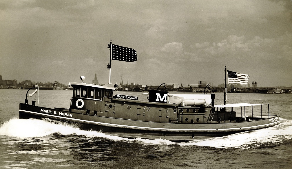
The Marie would be powered by a single direct reversing Winton 6-164 engine, a huge 15”x22” engine making a mere 550HP at 275RPM.  The 89’ tug was designed by Edmund J. Moran himself, and built at Pennsylvania Shipyards in Beaumont, Texas.  The low profile tug was designed for use in the New York State Barge canal, composed of the Erie, Champlain, Oswego, Cayuga & Seneca canals, all of which required the low profile due to numerous low bridges and whatnot.  When Marie S. Moran was constructed, Diesel engines were still being “figured out” so to speak, and companies would tend to try different engines and combinations.  Like many tugs of the era, the Marie would be retrofitted with a retractable wheelhouse later in her life (more on this later), and the original Winton would be replaced with a more reliable 12-567 engine.  The tug was sold foreign in 1961.  Two more similar tugs would be built in 1937, the Eugenia M. Moran and Elizabeth W. Moran, powered by Alco-Sulzer engines. Both of these would also be sold foreign in 1950’s as well.

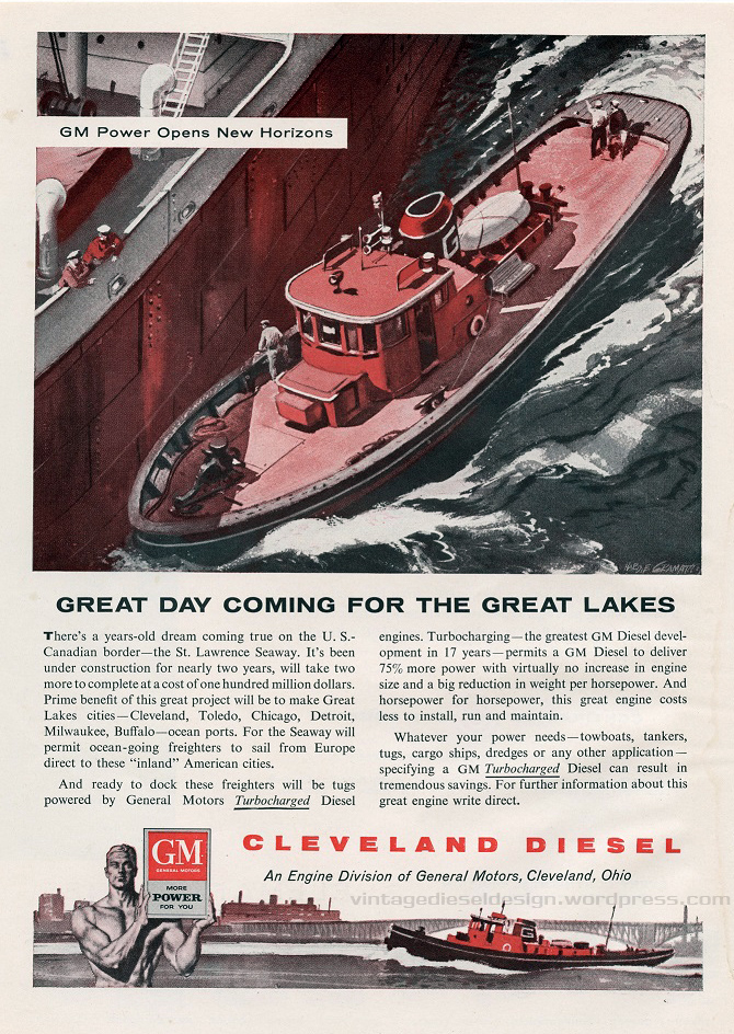
 Skip ahead just a few more years to 1938.  Electro-Motive, under GM introduced the new 567 engines, and Moran was looking for some more canal tugs, so the two would become one with the introduction of Thomas E. and William J. Moran.  A new relationship would be born as well, Moran Towing working with Tam’s Inc. and General Motors. 

The Thomas E. Moran on is on the slipways in Bay City, Michigan. It looks like both tugs were launched the same day! Click for larger. Courtesy of the Dave Boone Collection

The tugs would mark another milestone – breaking Tam’s, Inc. into the world of tugboats. While I do not know if they were the very first ones, they would be the ones that really set the pace. Tam’s was well versed in yacht design, as well as being a broker and insurance company. Working with Winton on yacht design would start the relationship with GM as well, being that GM now owned Winton. Beginning in 1938, and lasting for only about a year, General Motors marketed all three engine divisions (Winton {soon to become Cleveland}, EMC and Detroit) under the single “General Motors Diesel Engine Division”, even though the three companies were still operating individually.

The Thomas & William were featured in the 1940’s booklet “Diesel-Electric Vessels Powered by Cleveland Diesel”. Click for larger.
The brand new Thomas E. Moran on her sea trials, likely somewhere in Saginaw Bay. Click for larger. Courtesy of the Dave Boone Collection.

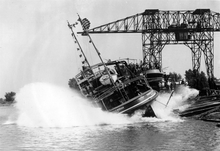
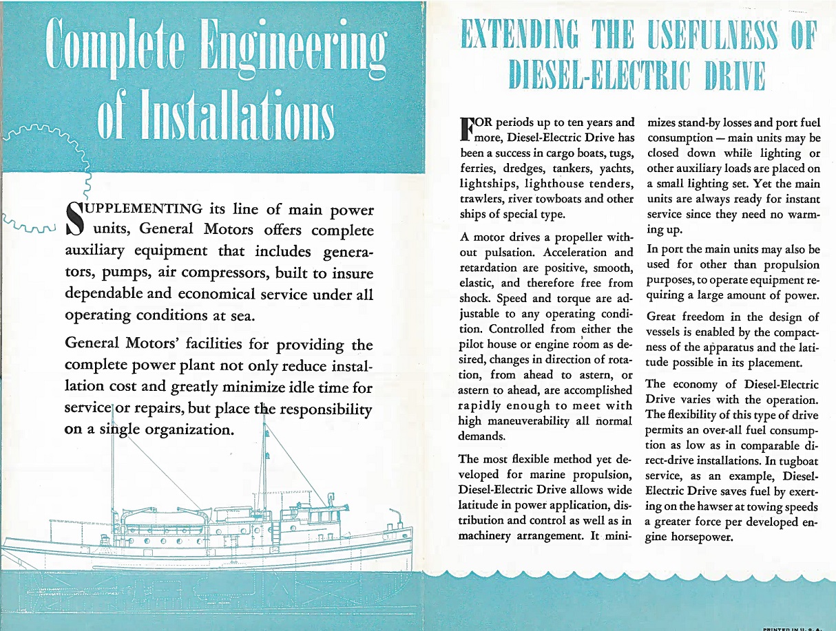
I was first introduced to the Thomas & William in detail when my partner in Cleveland research Jay Boggess showed me a scan of a GM booklet he had: “A New Conception of Diesel-Electric Drive”, which featured the two tugs in depth. Designed under Richard Cook at Tam’s, the tugs were 94′ 4 1/2″ long, with a 25′ beam. The all welded tugs were built in Bay City, Michigan at Defoe Boat & Motor Works. Diesel-Electric drive was not a new concept by any means, however using it with newer, medium speed engines was. Electro-Motive developed the new 567 engine in 1937 for railroad use, having learned from the lessons of the Winton 201A. However, interestingly enough, the first production 567 engines would be used in the Thomas and William, as quoted in EMD’s WWII era book “Diesel War Power”. The tugs used a pair of V8 567 engines, rated at 660HP at 750RPM each.

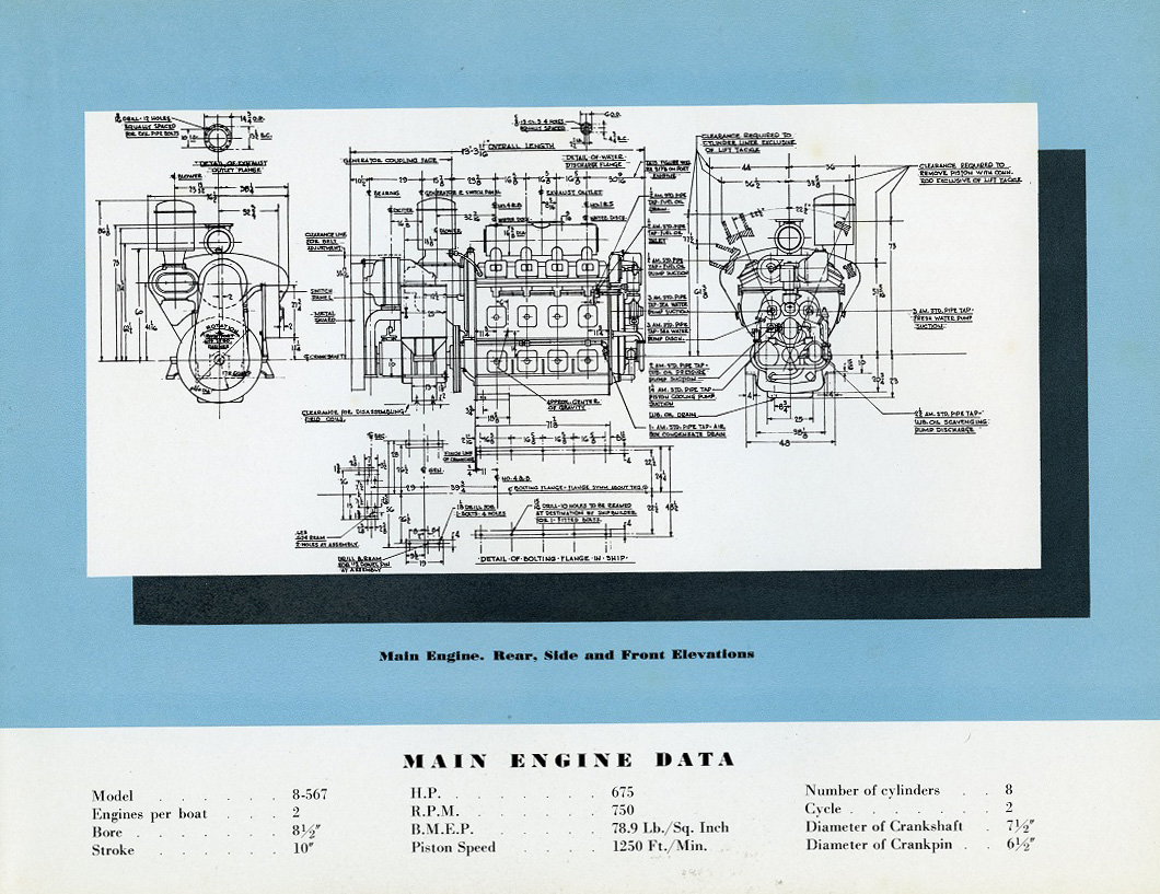
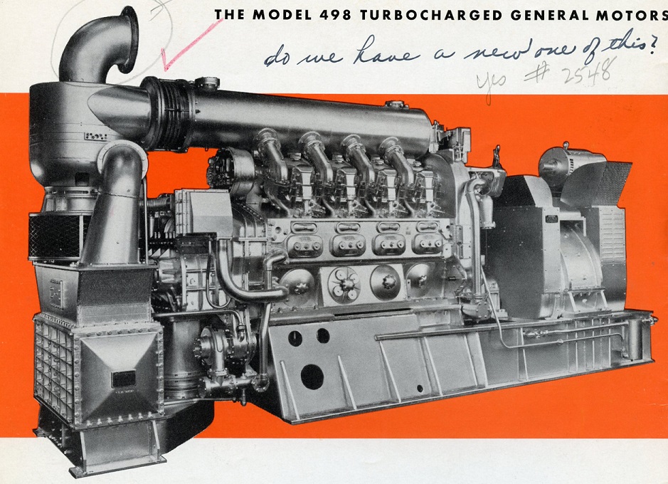
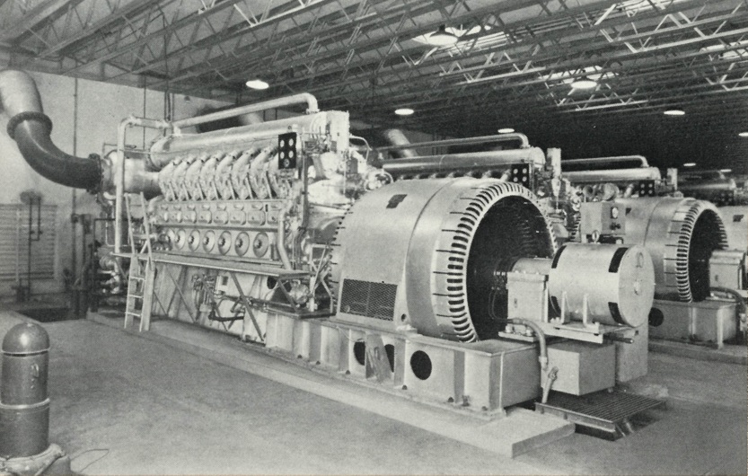
Photos of the engines from the “New Conception of Diesel-Electric Drive” booklet. Note how the engines do not look anything like the 567 we all know. While they did have a welded block, they did use more cast pieces in their construction, as well as individual covers for each power assembly. Click for larger.

Build sheet date for the engines. More on the name change shortly..

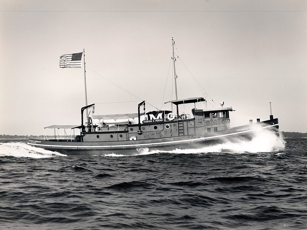
Thomas & William at home in the NYS Canal System. Click for larger. Courtesy of the Dave Boone Collection.

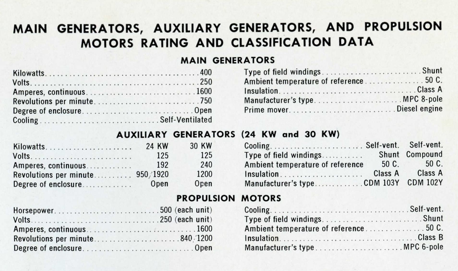
Electrically, the tugs used General Electric 400kW, 250 volt shunt wound main generators behind each of the 567’s, with belt driven 24kW exciter/shaft generators. General Electric also supplied the pair of 500HP propulsion motors. A common arrangement of the era was using two smaller motors, feeding into one reduction gear, supplied by Farrel-Birmingham. The arrangement was used on numerous fleet tugs throughout WWII. After the Thomas and William, Moran (along with James McWilliams Blue Line) would build several more tugs in 1939-1941 to virtually the same design, however they would be powered with single EMC 12-567 engines (Sagamore, Sheila Moran) and the last ones with Cleveland 12-278 engines (William J. Moran, Agnes A. Moran, Mary Moran, Sheila Moran), the later ones having a more normal, single level deckhouse (more on that later).

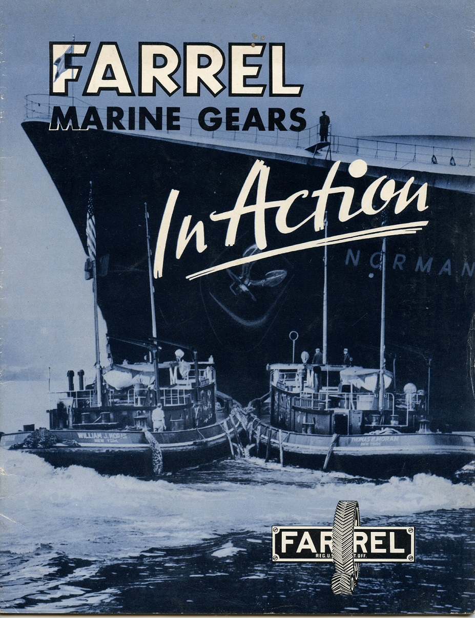
Farrel-Birmingham catalog pages showing the tugs. Click for larger.

Along with the 24kW shaft generators, the tugs each had a single Detroit 3-71, which drove a 30kW generator. The 71 was also a newly introduced engine in 1938. Click for larger.

A small booklet produced by GM featuring the new 567 engine. Ironically only the Thomas had the 567! Click for larger.

With World War II looming in the distance, the US Navy would requisition these tugs in 1940. I have long since been told that the Thomas and William were the prototype design for the YTB series that would be built in mass throughout the war. Part of me wonders if the Navy financed these in some way, with an agreement that they would be used during the war. But these details are likely lost to history. The Thomas would become the Namontack, originally classed as a Yard Net Tender (YN-46), Net Yender (YNT-614) and finally Yard Tug, Big (YTB-738). The William received the same treatment, and was named Wapasa, and also did time as a Yard Net Tender (YN-45), Net Yender (YNT-613) and finally Yard Tug, Big (YTB-737). After the war, the tugs would be returned (resold? I am not sure how those requisitions worked, if anyone knows, please drop me a line!) to Moran, however would be renamed. Originally the Thomas E. Moran, her new name was now the Harriet Moran. The William J. Moran became the Anne Moran.

The Anne Moran at home in the canal, made up in push gear with a grain barge (which looks to be an old motorship). The tugs had 4 control stations, the wheelhouse, the upper deck, the aft deck, and the engine room. Note the “box” on top. This was the upper wheelhouse to gain a little more height to see over the barge. The primitive wooden box was installed in the fall/winter and would fold up in inclement weather. Click for larger. Courtesy of the Dave Boone Collection.

After the war, Cleveland Diesel went heavy on marketing, producing numerous booklets and brochures. These are from the late 1940’s book “Commercial Vessels Powered by Cleveland Diesel”. Note that they used older photos of the Thomas and William, and airbrushed the original names out in favor of the new, post war renaming’s. Not only that, but they incorrectly spelled the one! An interesting feature of these tugs is the sliding heavy weather portholes, that would slide up the cover the large glass windows. Click for larger.

In 1956, Moran embarked on a modernization program for the canal tugs. The Harriet and Anne would both be repowered with single war surplus (from PCE vessels, unfortunately the records do not note which) Cleveland 1000HP 12-278A engines and Allis-Chalmers 814kW main generators, however the original propulsion motors were kept. Along with the repowering, the tugs received a new retractable wheelhouse. Introduced in 1950 by Lake Tankers Corp. on their tug Canal Cities, the retractable wheelhouse was a revolutionary advancement for working in the canal.  A large air or hydraulic cylinder raised and lowered the wheelhouse to see over the barge, but to “duck” when a bridge or other obstruction was approached.  Virtually all “modern” diesel canal tugs would be retrofitted with these by the mid 1950’s, with all new tugs being built with them from then on out. 

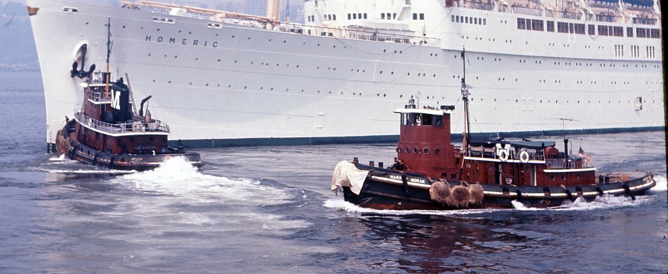
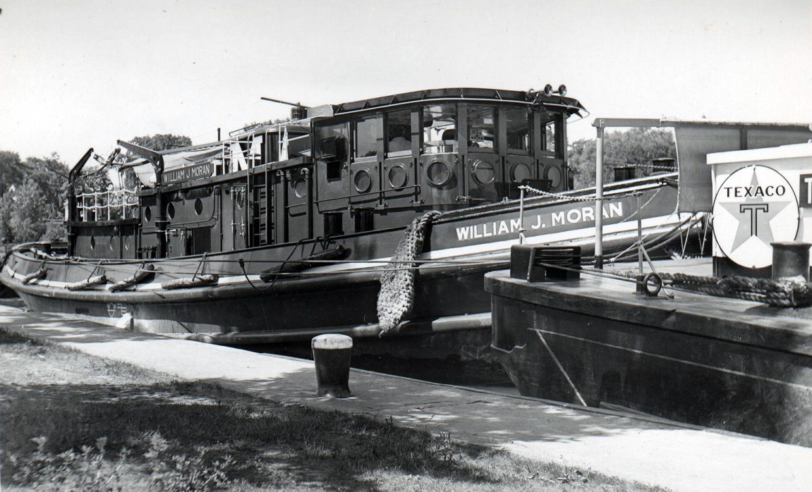
Now with her new retractable house, the Harriet Moran would still work the canal, but by the 1970’s was regulated to doing assist and barge work in the harbor. The Harriet and Anne would keep their stepped deckhouses, and sliding “portholes”, however the other Moran canal tugs mentioned above would get more modernized single level deckhouses, and square retractable wheelhouses. Note that the new wheelhouse fits inside the profile of the original one. Even the original Marie S. Moran of 1936 was retrofitted with one! Click for larger. Courtesy of the Dave Boone Collection.

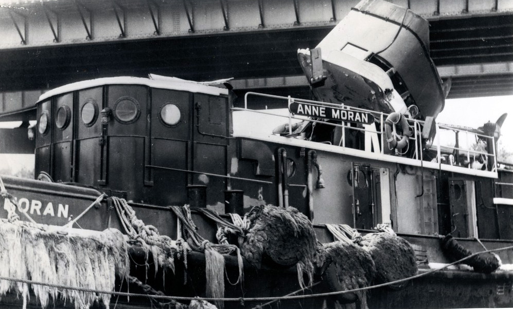
Unfortunately, working in the canal with a retractable wheelhouse had its downfalls. You need to pay attention! (To quote Buford T. Justice in Smokey and the Bandit: “Duck, or you’re gonna be talkin’ out yo ass!”) The wheelhouses essentially floated in a pocket, with some very basic guiderails. So when the captain forgets to drop the wheelhouse, the bridge is usually going to win, as what happened in 1965 to the Anne. Numerous canal tugs were decapitated over the years, but because they were so simple, the dents were pounded out, wires rerun, and back off to the races they went. I spent a few years working on a canal tug, and its an all hands on deck operation spotting for obstructions, especially high tension wires at night. Click for larger. VDD collection.

Typically a “last stop” for tugs working for Moran was to be put on the garbage barge run before being retired. The Anne is moving one of the DSNY scows in 1970. Click for larger. Courtesy of the Dave Boone Collection.

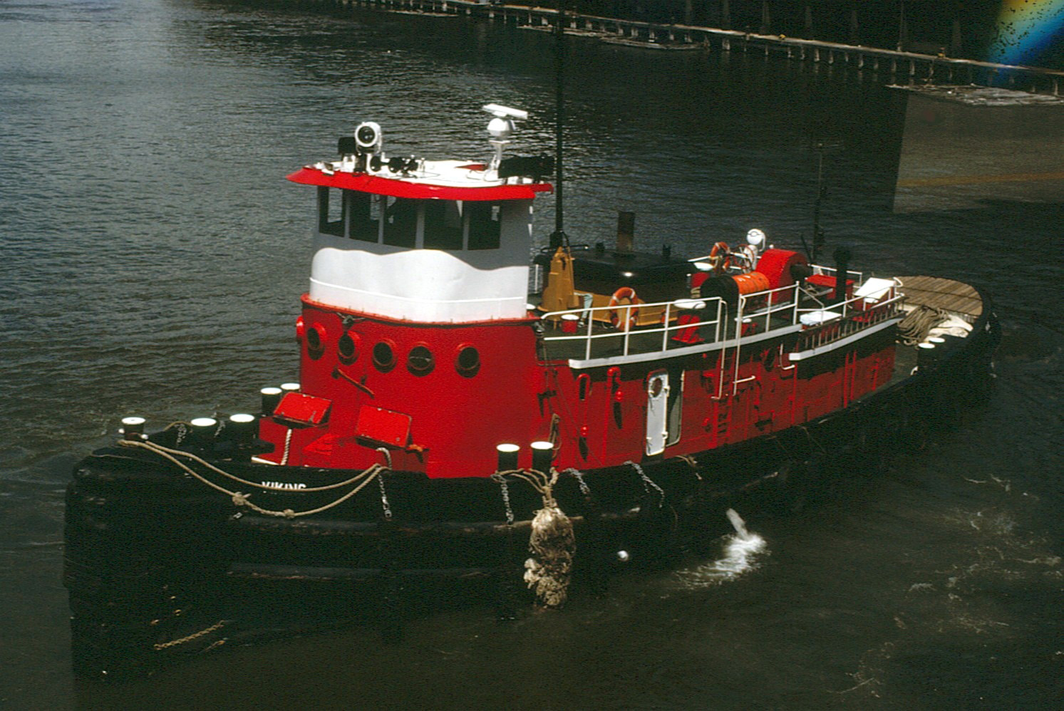
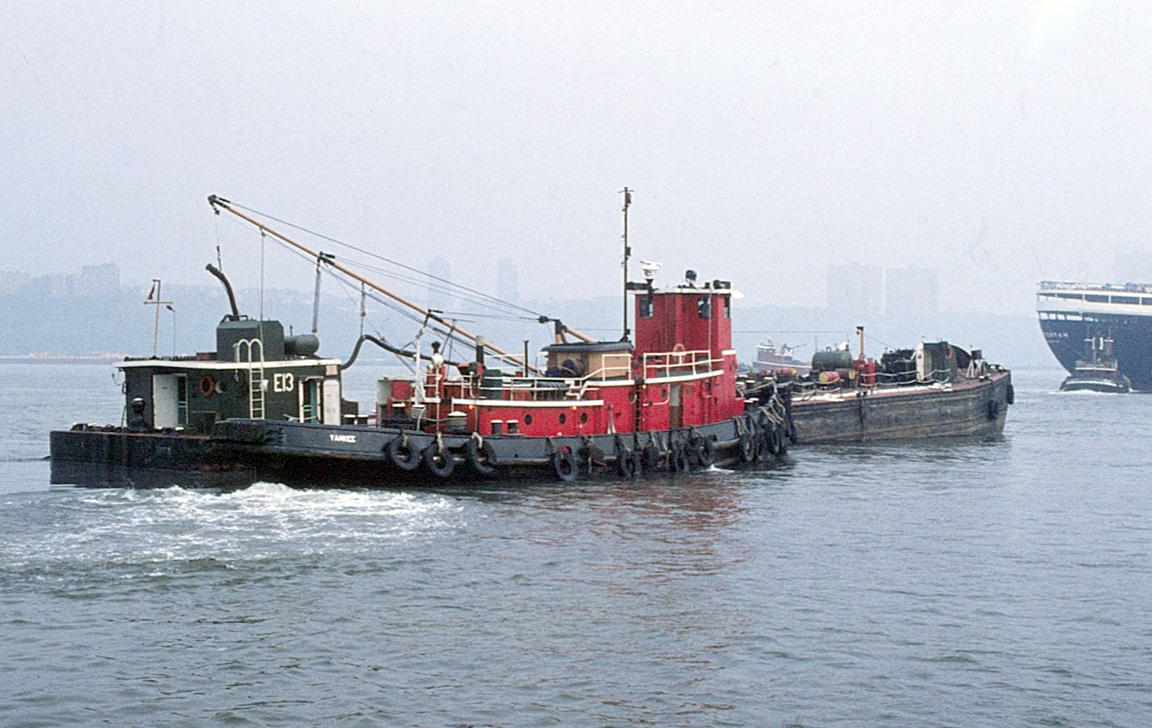
Moran would sell both of the tugs to Eklof Transportation in 1975/6 with the Harriet becoming the Viking, and the Anne the Yankee. Eklof would use the tugs for moving oil barges around the harbor for the next 15 or so years. Unfortunately, the road would end here for the Yankee (William J. Moran) and was scrapped in 1993. Our story does not end here though. Click for larger. Courtesy of the Dave Boone Collection.

Now the McAllisters Sharon Elizabeth in Georgetown, SC. Click for larger. Photo courtesy of Franz A. von Riedel.

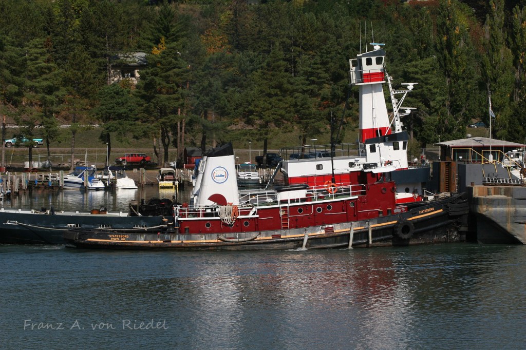
A small towing company, Georgetown Towing, based in Georgetown, South Carolina purchased the Viking, and named her as the Georgetown, doing ship and barge work in the area. McAllister Towing would purchase the company in 1999, and renamed the tug as the Sharon Elizabeth. Zenith Tugboat of Duluth, MN purchased the tug in 2005, and brought it up to the Great Lakes via the Erie Canal – right at home, 67 years after being built.

Now sporting Zenith’s stack colors, the Sharon Elizabeth is laying over in Troy, New York on her way to Duluth. Click for larger. Photo courtesy of Franz A. von Riedel.
Photo courtesy of Franz A. von Riedel.

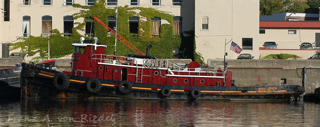
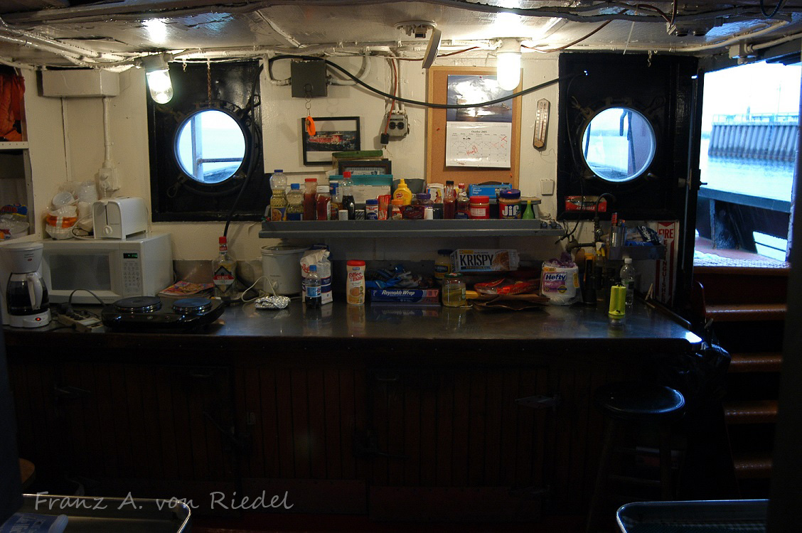
Lets take a quick walk through the Sharon Elizabeth, starting in the stern. I always wondered the reasoning behind the stepped deckhouse design. Entering in from the door, you head down a few steps into the galley, complete with giant cast iron Webb diesel stove that every tug and ship of the era had. Click for larger. Photos courtesy of Franz A. von Riedel.

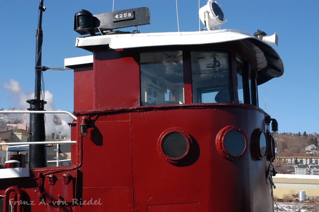
Canal tug wheelhouses are usually pretty spartan, simply because they lack any extra space. The Sharon’s wheelhouse had the typical Lakeshore Diesel-Electric control stands, and Benson electric steering, likely all installed during the 1950’s rebuild. Along the back wall is the running light panel, and the field amp/prop shaft RPM gauge and steering changeover switch. At some point in her life, Moran welded the sliding window portholes in a fixed position, and removed the tracks. It was not uncommon for canal tug wheelhouses to be kept in a semi-lowered position (especially when they get older and the system fails). The one on the Sharon is not all the way down here. Click for larger. Photos courtesy of Franz A. von Riedel.

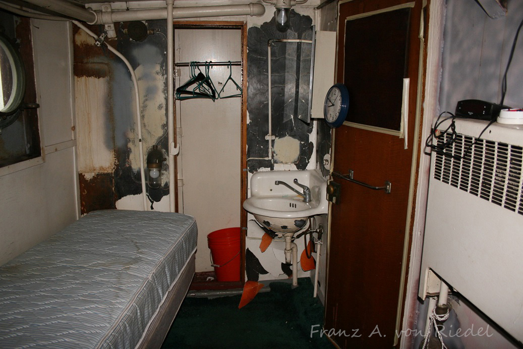
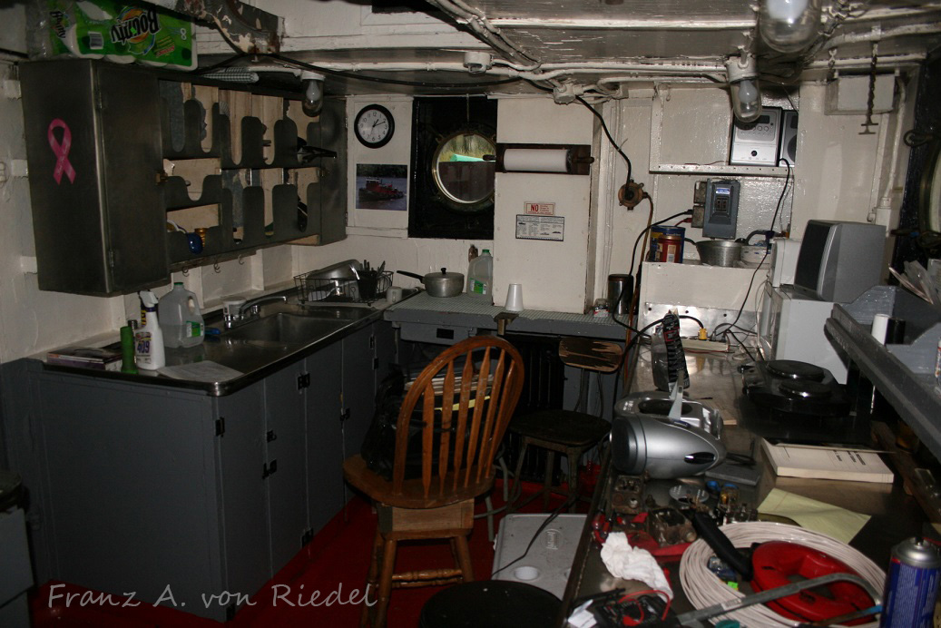
By the time smaller companies have these older boats, the staterooms are usually pretty tired – as often times the tugs are used as day boats, meaning no full time crews are living on the tug, which also means that maintenance starts to dwindle. For a canal tug however, these are some pretty big rooms! Click for larger. Photos courtesy of Franz A. von Riedel.

Photo courtesy of Franz A. von Riedel.

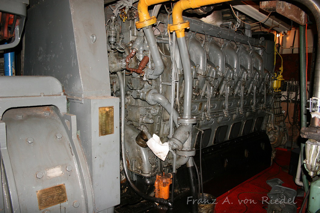
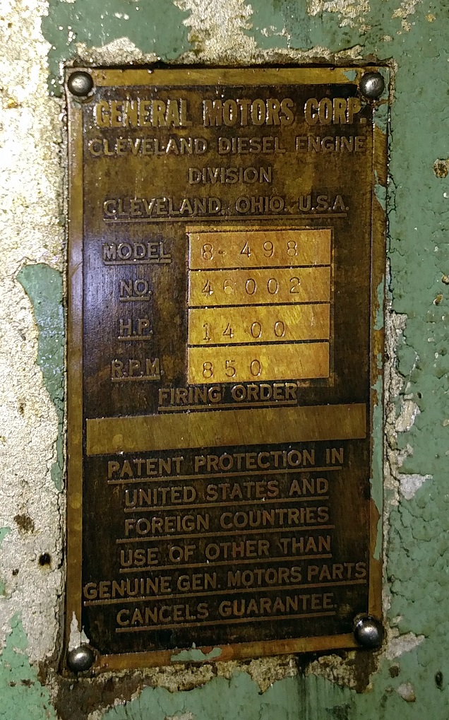
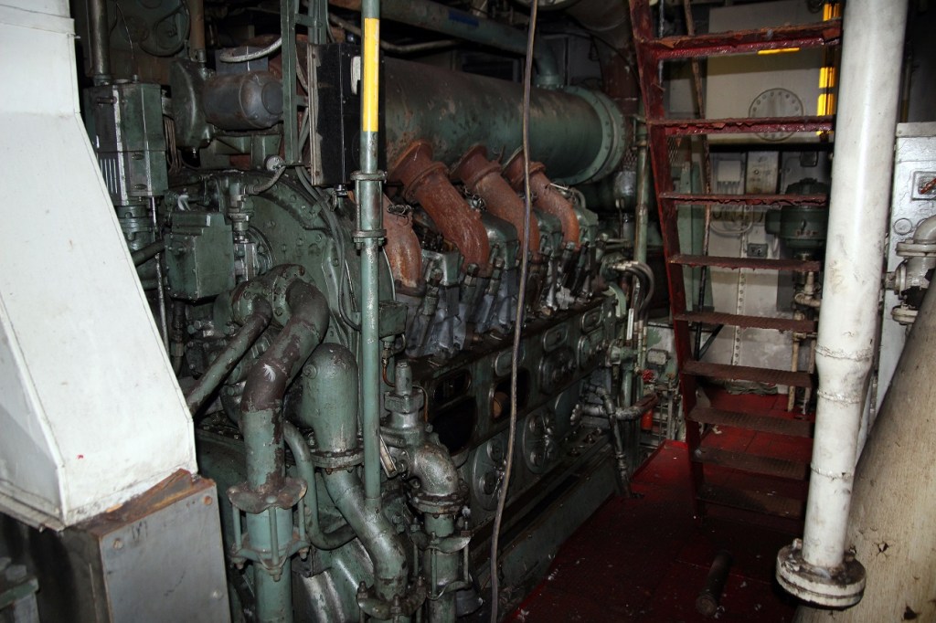
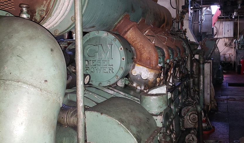
The Sharon had her twin 8-567 engines replaced in 1956 with a single Cleveland 12-278A removed from a Patrol Craft. An Allis-Chalmers main generator was utilized from a Destroyer-Escort, a common package used in Diesel-Electric tugs of the era. Click for larger. Photos courtesy of Franz A. von Riedel.

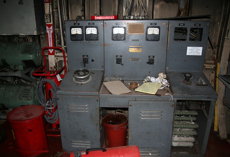
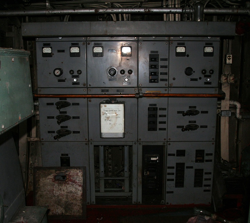
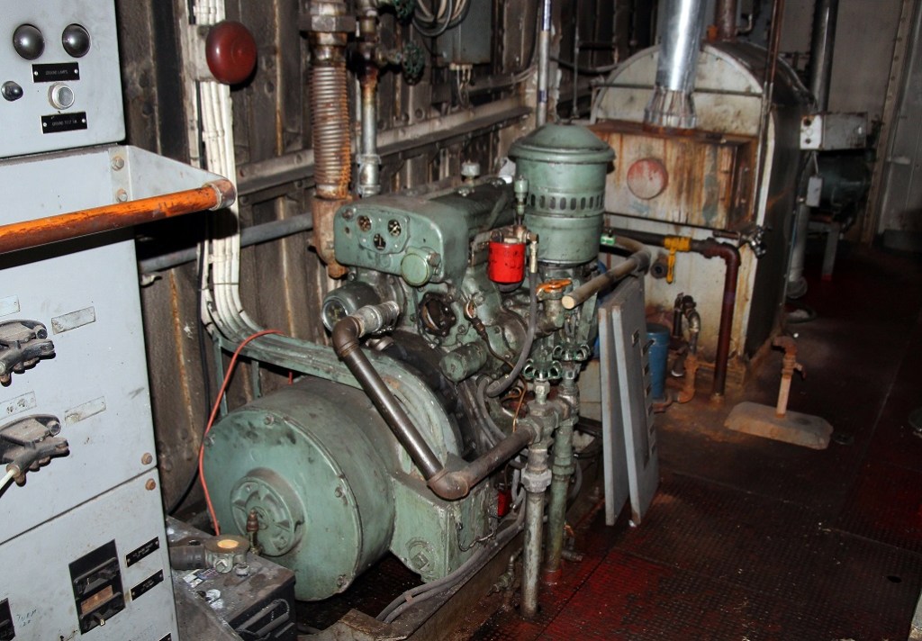
Electrically, the Sharon kept her original twin GE propulsion motors and Farrel-Birmingham reduction gear. A lakeshore propulsion panel connected the motors and generators. A Detroit 3-71 is seen in the forward end. Click for larger. Photos courtesy of Franz A. von Riedel.

Zenith renamed the Sharon Elizabeth as the Statesboro in Spring of 2006. For an almost 70 year old tug at the time, she still looked sharp. Photo courtesy of Franz A. von Riedel.
The tug was sold in the fall of 2006 to Busch Marine of in Carrollton, MI. The tug is being towed by their own tug, the Gregory J. Busch. Photo courtesy of Franz A. von Riedel.

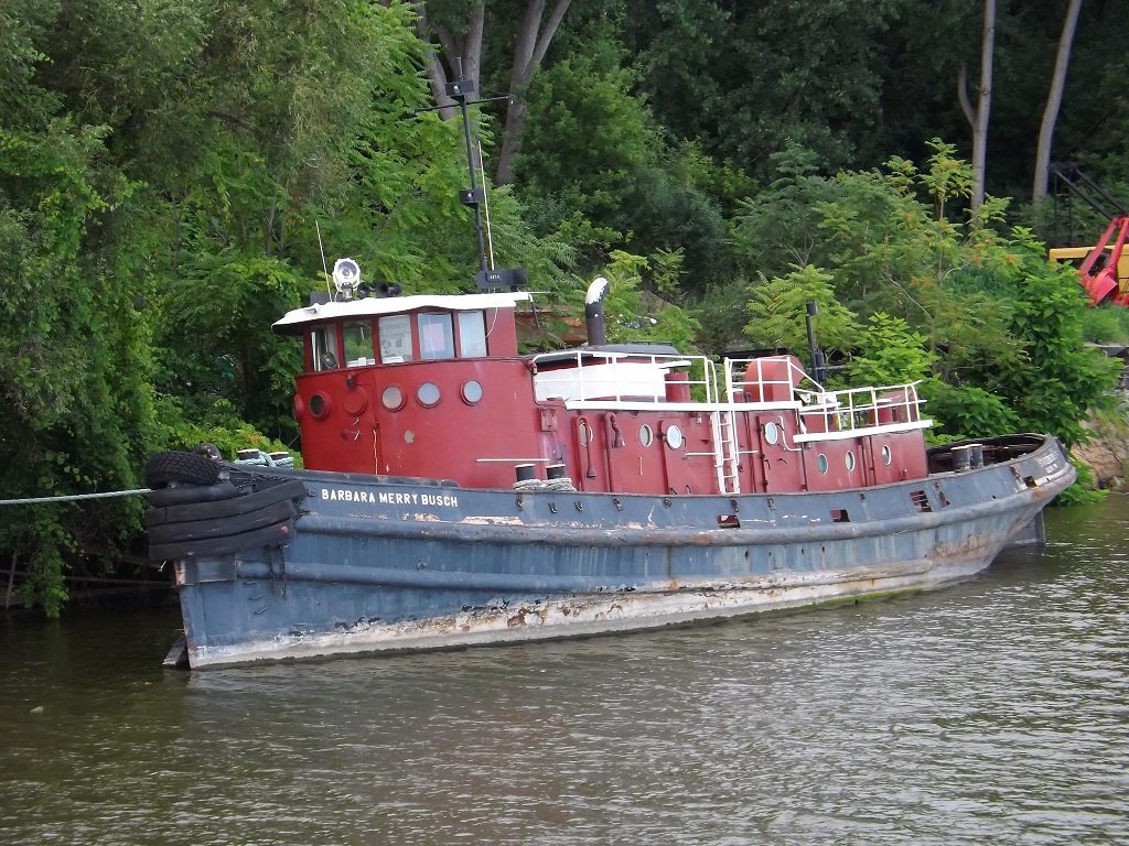
Busch Marine renamed the tug as the Barbara Merry Busch. The tug was tied up at their dock in the Saginaw River, only a few miles up from where she began her life in 1938. Unfortunately, the tug was never used by Busch, and she sits tied up listing heavily, waiting for what is likely an inevitable date with a scrapper one day. Even Busch’s large tug – Gregory J. Busch is laid up. This is another tug I would love to see inside, as she is powered by Alco 12-244 main engines.

Click for larger. Photos courtesy Todd Shorkey

Thomas E. Moran was featured in numerous GM advertisement’s.

While just a footnote in history now, the Thomas E. Moran will go down in history as being the first use of the EMD 567 engine, the engine that went on to become one of the most successful diesel designs even built, and used in countless tugs, locomotive’s and stationary applications. Moran would wind up working almost exclusively with Tams (and successor GM Design and Marine Design Inc.) over the next 30+ years, building some of the most recognizable tugs on the east coast – all powered with General Motors Diesel-Electric Drive. Following the Thomas and William, several 567 stationary gensets would be built, as well as a bunch of 12-cylinder models used in Navy and USCG tugs in 1939.

Be sure to visit our other pages highlighting historic vessels – https://vintagedieseldesign.com/historic-vessels/


Many thanks to Franz A. von Riedel for sharing his photos of the Sharon/Statesboro. Thanks to Dave Boone for sharing numerous photos with me over the years, Todd Shorkey, Isaac Pennock & Jay Boggess as always for scanning and sharing more then I can recount.

More reading –
https://tugboatinformation.com/tug.cfm?id=798
https://tugboatinformation.com/tug.cfm?id=802
https://gltugs.wordpress.com/barbara-merry-busch/
http://www.navsource.org/archives/14/22046.htm
http://www.navsource.org/archives/14/22045.htm

A Turbocharged Failure – The Story of the Cleveland 498, Part IV

Part IV, the final part of this series will be a photo documentation of the tug Idaho.

Be sure to view the previous parts:
A Turbocharged Failure – The Story of the Cleveland 498, Part I – Introduction
A Turbocharged Failure – The Story of the Cleveland 498, Part II – Engine Design
A Turbocharged Failure – The Story of the Cleveland 498, Part III – Engine Installations

By the early 1990’s, the Great Lakes Towing Company (GLTC) would have the only running Cleveland 498 engines left in the US (See note on the bottom). The Towing Company as they are known has a rich history dating back to its formation in 1899, consolidating several smaller tugboat companies on the Great Lakes. GLTC currently serves numerous ports across the Great Lakes, and is the largest user of Cleveland 278 (A and non A engines) left in the country.

Starting in 1907, the company began to build their own tugs in house, in their own shipyard. The yard, originally in Chicago, and moving to Cleveland is still churning out all new tugs for the company today, as well as doing outside work.

In 1931, the yard constructed Hull # 67, and named her the Idaho. GLTC had two sizes of tugs, the smaller, “Type I”, which were named after cities, and larger “Type II”, named after states. The Idaho would be the last new tug built until 2008.

The Idaho was originally powered by a single cylinder, 26″ x 28″ steam engine. The tug was 84′ 4″ long, 20′ beam and a 12’6″ depth. The tug was one of three that would receive a raised height wheelhouse for doing lake towing.

The Idaho after receiving her raised wheelhouse. Please note that this photo is not in my collection, simply one from my files. If anyone knows the photographer or archive please send me a message so it can properly be credited.
Ironically, one of the very first pieces of Cleveland Diesel ephemera I would add to my collection would be one depicting the new 498 powered tugs of the Great Lakes Towing Co.

In 1956, the Idaho was on the block to be converted to Diesel propulsion. The engine chosen was the new 498 from Cleveland Diesel, as outlined in previous posts. Cleveland Diesel Order #1640 was placed in early 1956, for a pair of left hand rotation, 1400HP, 8-cylinder 498 engines to convert the tugs Montana and Idaho (Montana was an identical sister, Hull #60 of 1929). The engine for Idaho, #46002 was shipped from the factory on 12/13/1956, having to only go a few miles up to the companies shipyard. The tugs would receive Diesel-Electric propulsion packages, utilizing WWII surplus Destroyer-Escort main generators and propulsion motors. Disaster struck the Idaho shortly after being rebuilt on 10/21/1960. The tug was assisting the lake ship C.H. McCullough, Jr. in Chicago, when the tug was sunk. She would be raised, dried out and put back in service. A photo of her being raised appears in Alexander Meakins “The Story of the Great Lakes Towing Co.”

The 498 powered tugs would never stray too far from the main yard in Cleveland, typically working the ports of Cleveland, Ashtabula, Toledo or Detroit. The porthole aft of the wheelhouse is the tugs small bathroom. Photo by Isaac Pennock.

Great Lakes Towing Company would ultimately have a quartet of 498 powered tugs. The Diesel-Electric Montana and Idaho, and the Clutch tugs Tennessee and Pennsylvania which were converted in 1960 from Steam. Montana would be retired in 2006, Tennessee in 2012 and the Pennsylvania in 2019. Ironically, the Pennsylvania would wind up receiving a replacement engine at some point in her life, originally out of the towboat Leila C. Shearer. This too was replaced with an EMD 12-645, however the conversion was never finished.

Sister tug Montana received the first 498 engine to be sold, seen here being lowered into the tug at the Cleveland yard. From Cleveland Diesel’s “More Power For You” brochure.

Noting that the last surviving 498 was likely nearing the end of her life, we reached out to the company to see about the possibility of documenting the engine and tug, and maybe see about preservation options. Unfortunately, we would be a touch too late. While the tug was still around, it was sitting laid up having suffered a catastrophic engine failure in 2016, however we were welcome to document her anyway.

The tug was laid up in Detroit for a few years, and was being used for parts for the other tugs in the GLTC fleet (while the engines were different, the tugs still share many parts between them).

The heart of the Idaho is her Cleveland 498 engine. Note the exhaust jumpers are rusty, having no water jacket around them, and by this point, no insulation either.
The tug had a WWII surplus, Allis-Chalmers 525V DC propulsion motor, rated for 1090kW at 720RPM. On top is a 120V DC shaft generator.
The power package installed in the Idaho. From Cleveland Diesel’s “More Power For You” brochure.
The propulsion switchboard. At left is a pair of excitation generators.
Also from the Destroyer-Escort is the propulsion motor. This was built by Westinghouse, and rated for 1225HP.
Farrel-Birmingham reduction gear, with a 4.233:1 ratio. The tug has a 102″ x 87″ stainless 3 blade propeller.
The portside, aft end of the engine room has the steering gear pump, as well as a motor-generator set. The fuel tanks are located behind the aft bulkhead.
Switchboard.
Portside of the engine, the air starter is mounted on the floor level. On top are the various gauges and governor.
Detroit Diesel 3-71 with a 30kW generator. In front is the tugs oil fired steam boiler for heating.
Air compressors.
The heart of the 498 is the De Laval turbocharger. The air intake filter is seen in the middle, with the compressor on top. A discharge tube feeds air into the intercooler on the bottom.
From the intercooler, the air fed into the roots blower (at left) from the bottom end. It was mentioned these engines sounded like helicopters.
Looking aft, the large cast cover is over the camshaft balancer, proudly displaying the maker of the engine.
Taking on ode from the 248 engine, the 498 used a two piece top cover. On the bottom right is the blowdown/safety valve. Former engineers for this boat mentioned heads and head gaskets were a big failure point being addressed often.
The reason the Idaho was retired. Shortly after startup, the #4 piston locked up, thus the connecting rod snapped, in turn swinging around and slamming into the airbox and both liners.
Unfortunately, parts for the 498 were long since unavailable, and a failure like this is typically a death sentence anyway, especially in an 80+ year old hull.
The hydraulic power pack and head tightening tool.
G tugs still have a tiller handle for rudder control, along with the Lakeshore throttle stands.
Wheelhouses were rather spartan, with a simple bench, small chart table and propulsion gauges. These tugs were only intended to do day work, with no real provisions of any kind.
These tugs were built for one purpose, docking ships, thus the low profile deckhouse. The stairs in front lead down into the forecastle.
A few basic bunks, lockers and a simple table in the bow.
The tugs official number, gouged into the steel 80+ years ago.
Great Lakes Towing exclusively used towing bitts manufactured by the Montague Iron Works in Northwest Michigan.
“G” tugs as they are known in the lakes, got their name from the large stack insignia.
The Idaho returning from a job in her last year in service on the Detroit River. Photo by Isaac Pennock.
Removal of the stack insignias traditionally mean the end is near. This was likely the last photo of the Idaho in one piece. Bill Kloss Photo.

Unfortunately, all things must come to an end. In January of 2019 the tug was towed back to Cleveland, and with the last few usable parts removed, the tug was scrapped. We can’t thank the Great Lakes Towing Company enough for allowing us to photo-document the tug.

With only 58 engines built, and being that virtually all of the engines stateside were replaced long ago, it is highly unlikely any of the foreign sold engines remain. We heard a rumor of one driving a water pump in Egypt, but again, this would have had to have been a relocated engine, and is highly unlikely it exists. Somebody please prove us wrong!

That wraps up our four part series on the Cleveland Diesel 498 engine. Please be sure to view the previous posts on this engine, linked on the top of this page. I will say it again, if anyone has any 498 manuals, brochures, stories, parts, anything, please get in touch with us. Should anything new arise, we will make another follow up down the road.

2022 Update – At some point this year we will post another part in this series, with some additional information we found.

A Turbocharged Failure – The Story of the Cleveland 498, Part III

Part III of A Turbocharged Failure will be fairly straightforward – a listing of ALL 498 engines built.

Be sure to view the previous two parts:
A Turbocharged Failure, Part I – Engine History
A Turbocharged Failure, Part II – Engine Specifications

Production of the Cleveland 498 commenced with the first engine shipped in May of 1956. Most production would take place in the fall of 1956 (16 engines built), and the summer of 1957 (17 engines built). 1958 saw only a pair of engines, a trio in 1959, and the last 4 were built in 1960. A total of 29 8-cylinder, 9 12-cylinder, 17 16-cylinder and 3 test engines (one 8, and two unknown) were built over the course of production, for a grand total of 58 engines.

A brochure for the engine issued not long after being announced at Powerama. Click for larger.


1) Tug Montana – Great Lakes Towing Company, Cleveland, Ohio
Engine 46001, Shipped 5/2/1956, Order #1640, 8-498, 1400HP/850RPM

2) Tug Idaho – Great Lakes Towing Company, Cleveland, Ohio
Engine 46001, Shipped 12/13/1956, Order #1640, 8-498, 1400HP/850RPM

Great Lakes Towing Company needs no introduction here, they are the largest tug company performing shipdocking on the Great Lakes, using “G Tugs”.   We will do a more detailed feature on these down the road.   Great Lakes put in the very first order for 498 engines, with the first one going into the tug Montana.   Montana was built in 1929, with a single cylinder steam engine.   Idaho followed a few months later.  Idaho was the last “new” tug built, in 1931.   Both tugs were identical and built-in house, receiving electric drive propulsion packages using surplus Destroyer-Escort generators and propulsion motors***.   The Montana was retired and scrapped in 2006, and the Idaho was scrapped in 2019.  The 4th and final part will be dedicated to the Idaho

Tug Idaho shortly after being converted to Diesel power. VDD Collection.

————

3) Tug Hoboken – Delaware Lackawanna & Western Railroad – NY, NY
Engine 46003, Shipped 10/31/1956, Order #1807, 8-498, 1400HP/850RPM

4) Tug Buffalo – Delaware Lackawanna & Western Railroad – NY, NY
Engine 46004, Shipped 11/30/1956, Order #1807, 8-498, 1400HP/850RPM

5) Tug Syracuse – Delaware Lackawanna & Western Railroad – NY, NY
Engine 46005, Shipped 12/28/1956, Order #1807, 8-498, 1400HP/850RPM

6) Tug Utica – Delaware Lackawanna & Western Railroad – NY, NY
Engine 46006, Shipped 1/14/1957, Order #1807, 8-498, 1400HP/850RPM

7) Tug Nazareth – Delaware Lackawanna & Western Railroad – NY, NY
Engine 46007, Shipped 1/21/1956, Order #1807, 8-498, 1400HP/850RPM

Delaware Lackawanna & Western placed an order for 5 Diesel-Electric tugs with Bethlehem Steel of NY, built to General Managers Association (GMA) design for moving carfloats in NY Harbor.   Erie Lackawanna started to sell off the tugs in the early 1970’s, these were the first to go, and every one of them was repowered not long after being sold (all being repowered by the early 1980’s).  Two would go on to get GE engines, two would get Alcos, and the last an EMD.  The Utica, the last survivor, is now working in Panama.   These tugs will be covered extensively in my upcoming book on Railroad Tugs, coming out later this year.  

Diesel Times/J. Boggess Collection

————

8/9) Towboat Lelia C. Shearer – O.F. Shearer & Sons, – Winchester, KY
Engines 46008, 46009, Shipped 10/19/1956, Order # 1883/1884, 8-498, 1230HP/750RPM

Hillman Barge & Construction both designed and built this 2700HP diesel-clutch twin screw towboat for the O.F. Shearer & Sons company.   She was repowered in 1964 with a pair of EMD 16-567C engines.  The towboat kept her name through several companies and was finally scrapped in 2014.    This was the first 498 powered towboat. 

Diesel Times/J. Boggess Collection

————

10/11) Tug M.P. Anderson – Brown & Root, Inc.
Engines 46010, 46011, Shipped 7/30/1956, 731/1956, Order # 1974, 8-498, 1400HP/850RPM

M.P. Anderson was designed by Brown & Root and built by Gulfport Shipbuilding.  This 123-foot, twin screw, Diesel-Electric tug worked in the Gulf for most of her life and was also repowered with a pair of EMD 16-567C engines, with reverse-reduction gears in place of the electric drive.  She is now working in Baltimore as the Austin Krause (and has one of the largest tug engine rooms I have ever been in).

The M.P. Anderson was covered in the June 1959 issue of Diesel Times. J. Boggess Collection

————

12) Tug William C. Gaynor – Great Lakes Dredge & Dock Co.
Engine 46012, Shipped 9/11/1956, Order # 1956, 8-498, 1400HP/850RPM

This 94’ tug was designed by Joe Hack under Cleveland Diesel for Great Lakes Dredge & Dock.  The tug was built by DeFoe shipbuilding and spent her entire life in the Great Lakes doing dredge work.   Today she is working (under her original name) for Sarter Marine in Sturgeon Bay, WI.   The tug was repowered with an EMD 12-567C in 1990.

————

13) Test Engine
Engine 46013, 8-498

————

14/15) Towboat Gulf Inlander – Gulf Oil Corp.
Engines 46014, 46015, Shipped 10/26/1956, 11/30/1956, Order 1923/1924, 8-498, 1400HP/850RPM

Gulf Inlander was a twin-screw towboat built by St. Louis Shipbuilding for Gulf Oil.   Now known as the Mary Lynn, she was repowered and now has a pair of EMD 16-645 engines. 

Diesel Times/J. Boggess Collection

————

16-26) All engines 8-498 Non-Magnetic, 1400HP/850RPM

MSO-521 Assurance, Engine 46016, Shipped 10/28/1957, Order # 62562
MSO-519 Ability, Engine 46017, Shipped 7/29/1957, Order # 62562
MSO-520 Alacrity, Engine 46018, Shipped 8/5/1957, Order 62562
MSO-519 Ability, Engine 46019, Shipped 6/22/1957, Order 62563
MSO-520 Alacrity, Engine 46020, Shipped 8/7/1957, Order 62563
MSO-521 Assurance, Engine 46021, Shipped 9/10/1957, Order 62563
Naval Supply Depot (spare engine?), Engine 46022, Shipped 11/30/1960, Order 62672
MSO-519 Ability, Engine 46023, Shipped 7/31/1957, Order 62572
MSO-520 Alacrity, Engine 46024, Shipped 8/27/1957, Order 62572
MSO-521 Assurance, Engine 46025, Shipped 11/6/1957, Order 62572
Naval Supply Depot (spare engine?), Engine 46026, Shipped 11/30/1960, Order 62675

USS Ability MSO 519 stricken 1971
http://www.navsource.org/archives/11/02519.htm
USS Alacrity MSO 520 sold for scrap Dec 1979
http://www.navsource.org/archives/11/02520.htm
USS Assurance MSO 521 scrapped in Dec 1979
http://www.navsource.org/archives/11/02521.htm

All we know about these three minesweepers with non-magnetic 498s is what we can find in Wikipedia & Navsource. We have no idea how long the 498s lasted or how well they did – it is likely the reason these ships were retired was because of the 498’s.  Since these three ships were scrapped over 40 years ago, we suspect that information is lost to the ages.  BUT, if there are any ex-Navy sailors out there, drop us a line.    

Diesel Times/J. Boggess Collection

————

27/28) Towboat Eleanor Gordon – Two engine order, shipped 4/24/1957, Order 2039/2040, 8-948, 1400HP/850RPM. 

Designed and built by Nashville Bridge Co. for Mid America Transportation Company.   This 149’ towboat was powered by the pair of 498 engines with Falk reverse reduction gears.  Apparently Mid-America was so displeased with these engines that the towboat was repowered within 18 months. 

Diesel Times/J. Boggess Collection

The engines were sent back to Cleveland, who rebuilt them and reshipped them under a new order to Great Lakes Towing Company, who installed them into a pair of tugs, the Pennsylvania and Tennessee

 Pennsylvania would be one of the tugs assigned to work all the way down in Florida on a Navy contract in the 1990’s.   Tennessee was scrapped in 2012, with the Pennsylvania being scrapped in 2019.  The Pennsylvania was repowered with an EMD 12-645, however the repower was never completed before GLT decided to scrap her (?). 

Tennessee was an identical sister to the Pennsylvania, and also worked in Florida.  Both of these tugs were the only “G” tugs to have fixed Kort nozzles, with 102” wheels. 

Tug Pennsylvania
Engine 46027, Shipped 11/30/1959, Order 3936

Tug Tennessee
Engine 46028, Shipped 11/30/1959, Order 3937

The Pennsylvania and Tennessee on the job in the early 1970’s. VDD Collection.

————

29) Tug Alexander Wiley Robinson Bay, St. Lawrence Seaway Development Corp.
Engine 46029, Shipped 11/15/1957, Order 2573, 8-498, 1400HP/850RPM

Robinson Bay is a 103’ Diesel-Electric ice breaking tug designed by Merritt Demarest for use in the St. Laurence Seaway.   The tug was repowered by Great Lakes Towing in 1991, who kept the engine as a spare parts source.  The tug is now powered by a Cat 3606 with a 1750HP GE 581 propulsion motor. 

The Robinson Bay at work in Northern New York. Will Van Dorp Photo.

————

30) Development Engine
Engine 51001. 12-498S

————

31/32) Towboat Cypress, Chotin Transportation
Engines 51002, 51003, Shipped 8/31/1956, 12-498, Order 1653/1654, 2100HP/850RPM

Cypress was a 140’ towboat for the Chotin Transportation Company designed and built by J&S Shipbuilding.   The towboat has been out of documentation for some time and repowering/disposition is unknown.

Diesel Times/J. Boggess Collection

————

33) Tug Ralph E. Matton, John E. Matton & Sons, Cohoes, NY
Engine 51004, Shipped 7/31/1957, 12-498, Order 1726, 2100HP/850RPM

Ralph E. Matton was a New York Canal tug, designed and built by Matton.  The tug was repowered with an EMD 16-567C, and later became the Mary Turecamo, and Albany.  It was scrapped about 15 years ago. 

Courtesy of Dave Boone

————

34) Tug Spartan, James McWilliams Blue Line, NY, NY
Engine 51005, Shipped 9/14/1956, 12-498, Order 1893, 2100HP/850RPM

Spartan was a NY Canal tug, designed by Cleveland Diesel (Joe Hack) and built by Calumet Shipyard.   The tug became part of the Ira Bushey & Hess family of companies and was reefed in 1986. 

VDD Collection

————

35) Tug Matton #25, John E. Matton & Sons, Cohoes, NY
Engine 51006, Shipped 10/20/1956, 12-498, Order 1939, 2100HP/850RPM

Matton 25 was a New York Canal tug, designed and built by Matton.  The tug was repowered with an EMD 16-645, and later became the Joan Turecamo, and Everglades of Seabulk Towing.  It was reefed in 2017.

————

36) Tug Matton, John E. Matton & Sons, Cohoes, NY
Engine 51007, Shipped 4/29/1957, 12-498, Order 2210, 2100HP/850RPM

Matton was a New York Canal tug, designed and built by Matton.  The tug was repowered and later became the Kathleen Turecamo, and Troy.  It was reefed in 1990.

Courtesy of Dave Boone

————

37) Test Engine
Engine 51008, Order 3133

————

38) Gen-Set, Bell Telephone Co., Philadelphia, PA
Engine # 51009, Shipped 7/17/1957, Order 2118, 12-498, 1840HP/720RPM

————

39/40) Towboat Oliver C. Shearer, O.F. Shearer & Sons, Cedar Grove, WV
Engines 51010, 51011, Shipped 7/14/1960, Order 5058/5059, 7/21/1960, 12-948, 2100HP/800RPM

Shearer returned for another set of engines for a second towboat, the Oliver C. Shearer.  She was designed by Friede & Goldman Inc. and built by Marietta Manufacturing.   The towboat was repowered in 1965 with EMD 16-567C’s and has since been repowered several times with EMDs.  The towboat is still in service under her original name. 

Diesel Times/J. Boggess Collection

————

41) Development Engine
Engine 57001, Order 4150, 16-498S

————

42/43) Towboat Mark Eastin, West Kentucky Coal Co., Madisonville, KY
Engines 57002/57003, Order 1775/1776, Shipped 12/14/1956, 11/30/1956, 16-498, 2800HP/850RPM

The 177’ Towboat was at the time, the most powerful twin screw towboat on Inland Rivers.  Repowered in 1969 with EMD 16-645 engines.   In service today as the Kevin Michael

Diesel Times/J. Boggess Collection

————

44-53) Gen-Sets, Cia Cubana de Electricidad, Havana, Cuba
All engines are 16-498, 2850HP/720RPM, Order 2361

Engine 57004, Shipped 7/13/1957
Engine 57005, Shipped 7/19/1957
Engine 57006, Shipped 7/31/1957
Engine 57007, Shipped 8/6/1957
Engine 57008, Shipped 8/30/1957
Engine 57009, Shipped 8/31/1957
Engine 57010, Shipped 9/14/1957
Engine 57011, Shipped 9/21/1957
Engine 57012, Shipped 9/26/1957
Engine 57013, Shipped 9/30/1957

The largest order of 498 engines were these stationary 2000kW engines for a Cuban powerplant.   It is unknown how long, or if they still exist.   Anybody in Cuba want to go exploring for us? 

Diesel Times/S. Zelinka Collection

————

54/55) Gen-Sets, Saudi-National, LTD, PEX-583007
Engines 57014, 57015, Shipped 12/3/1958, 12/12/1958, Order 2982, 16-498, 2800HP/720RPM

————

56-58) Dredge Alaska, Great Lakes Dredge & Dock

Pump Engines
Engines 57016, 57017, Shipped 9/24/1959, Order 3756, 3757, 16-498, 2770HP/800RPM

Gen-Set
Engine 57018, Shipped 12/28/1959, Order 3760, 16-498, 2800HP/800RPM

Hydraulic Dredge Alaska used a trio of 498 engines.  Two engines drove the main pump drive unit, with the 3rd driving three generators, a 1250kW, 500kW and a 200kW, all on a common frame.   The Alaska is still in service, but of course was repowered, and currently has EMD 710 engines. 

Diesel Times/J. Boggess Collection


While most of the above users of the 498 were featured in a dedicated issue of Cleveland Diesel’s newsletter Diesel Times, the 9/1957 issue showcased the current maritime users of the engine. Click for larger.

Coming up in the final part of A Turbocharged Failure will be a post dedicated to the Great Lakes Towing tugboat Idaho, the last known 498 engine to be in use.

Thanks to my Cleveland Research Partner J. Boggess for proofing and sharing the above issues of Diesel Times.

A Turbocharged Failure – The Story of the Cleveland 498, Part II

In this second part of A Turbocharged Failure, we will go through some design features of the engine.  What better way to do this then to simply go through the engine manual and show a few key areas of the engine design.  Numerous additional photos of the 498 will appear in Part IV. 

Be sure to view the other parts of this series:
A Turbocharged Failure, Part I – Engine History
A Turbocharged Failure, Part III – Uses and Installations

The initial “catalog photo” of a production 12-498, with a Falk MB series reverse-reduction gearbox.

I have two versions of the 498 manual – both of which are titled as “preliminary” manuals.   The older version, which is undated and likely from around 1957, and lists 4 models of the 498; a 6-, an 8-, a 12- and 16-cylinder.   Like all manuals, an end view diagram is included, however this is a rather primitive, hand- drawn sketch. 

Engine cross section drawings. A colorized version would never be done. Click for larger

By the time the second edition was printed, dated for July of 1960, an all-new diagram was made including outlining various parts of the engine.   Along with this, several additional diagrams appear in the manual, as well as some more photos of various engine parts and repair techniques. At some point the 6-cylinder version was dropped from documentation, and would ultimately never be built.

Engine data and ratings – Click for larger

Engine Operation
Like all Cleveland engines, a simple lever is attached to the injector linkage.  A small thumb latch allows the lever to control the engine with no governor input.  When unlatched, the governor takes over all control of engine operation, used in conjunction with whatever remote propulsion control system is used.   On the 498 (and some Cleveland 567’s) equipped with reverse reduction gears, a second lever was added to control the air clutch, so that propulsion speed and direction could be controlled right at the engine.  498 engines were air-started- using an air motor, unlike the 278A engines which had direct air start into the cylinders.  

Engine operating levers on the 498. Click for larger

Crankcase
Like the previous Cleveland models, the 498 used an all-welded crankcase of various forged parts and steel plate.  A balanced, alloy steel crankshaft is used, interestingly enough the 12-cylinder crankshaft did not have any counterweights.  The crankshaft is drilled for oiling the connecting rod main bearings and wrist pins.  A vibration damper and balancer are mounted on the front end of the engine. 

Pistons, Connecting Rods & Liners
One of the biggest sets of improvements to the 498 engines from the previous 278A – are actually a few concepts borrowed from sister division EMD and the 567C engine. 

While the 278A and all previous models used a semi-water deck style liner (like the EMD 567 though the “B” block) – the 498 used a sealed liner which was attached to a water manifold in the airbox by a jumper (much like the 567C). 

A look in through the crankcase inspection cover at the connecting rods, showing the “pee pipe” attached to the lower end of the liner for piston cooling.

Again, borrowing from EMD, the pistons are a two-piece, trunk style floating piston (introduced on the LST 12-567 in WWII), whereas the 278A used a more traditional one-piece piston and a wrist pin.  On the floating piston, the piston itself sits on a thrust washer, which in turn sits on the piston carrier attached to the connecting rod.  Again, departing from the 278, Cleveland adopted the “pee pipe” piston cooling scheme EMD used since the first 567 of 1938, as opposed to the drilled connecting rod of the 278 & 268, which directed cooling oil from the crankshaft to the bottom of the piston. In the 498, the drilled connecting rod is only used for oiling the bearings and wrist pin.

Piston cooling on the 498 (top) used a drilled connecting rod to lubricate the bearings and wrist pin, however used a jet of oil which sprayed into an orifice directing oil into the cavity below the piston crown. The 278 (bottom) simply used the drilled connecting rod to lubricate everything, and used a spring check plate to retain oil in the crown.

The connecting rod of the 498 used a strap style of “cap” to contain the bearing and connect to the crankpin.  Like all Cleveland’s, each connecting rod used its own bearing on the crankpin, unlike the EMD engines which use a shared crankpin and bearing set by use of the fork and blade connecting rods. This allowed the EMD to be a slightly shorter length overall, as the cylinders were directly opposite each other, versus slightly offset on the Cleveland.

Cylinder Heads & Exhaust
Again, sharing with previous Cleveland models, the 498 used individual external heads, however these had some upgrades.  One of the big downfalls with the 278A style head, is there is a half-circle seal against the back of the head, which seals the cam pocket to the head.  Unfortunately, this is a major source of oil leaks.  The Navy devised a tool in the 1950’s to help combat this problem – a bracket clips into the injector control pocket on the block and a set screw presses the head back into the pocket, thus compressing the seal before the head is torqued down.  The 498 head had a specific tab on them (visible in the above photo of the operating levers), in which a bolted clip catches, allowing one to compress the head back into the seal.   The head itself was also torqued down in an interesting way. The head used stretch bolts, in which a special hydraulic tool was attached to pick up on the bolt before it was tightened down. The 498 returned to a two-piece valve cover design like the Winton 248 used.  The fuel lines were also moved inside now. 

Looking down on the cylinder head, which is a bit more cramped then those on the 278 family. Both fuel lines are now inside the engine, connected to main fuel lines under the exhaust manifold. The 498 used a two piece cover, like the original Winton 248 engine (I wonder if they are the same castings..). The new head design uses a combination safety and test valve, which were separate valves on the 278. EMD did not utilize these valves, which open should any excessive pressure build while the engine is running, preventing a bent connecting rod or worse. Note that the exhaust jumper has some sort of spray on insulation.

The hydraulic tool for tightening the head bolts was a rather simple process. The tension shaft is threaded onto the top portion of the stud, the tool is slipped over the tension shaft, and a nut on top secures it together. The tool is pumped up to 5,000PSI, and the actual nut holding the head down is tightened with the socket handle inside of the tool. The later 1960 manual indicates that these could also be manually torqued down to 1,030 ft. lbs. Click for larger.

A slight revision on the exhaust jumpers as well was devised.  Previous engines used a completely water- jacketed jumper (the older manual incorrectly stating that the 498 had this as well), however with the 498, it was preferable to keep the exhaust gases as hot as possible entering the turbocharger – thus no water jacketing on the exhaust jumper. A small pipe exits the head and carries water to the main exhaust manifold, which was still water jacketed.   The main exhaust manifold itself used diffuser sections to carry the exhaust gas to the turbocharger. 

Camshaft, Accessory and Governor Drive
Nothing all that special going on here.  The water pumps and blower are driven off the accessory drive on the front of the engine.  The camshafts are driven from the rear end of the engine by the crankshaft through a set of gears.   6- and 8-cylinder engines use one-piece camshafts, with 12- and 16-cylinder engines having two-piece camshafts.  On the forward end of the camshafts, the left side has a vibration damper (not used on the 12-cylinder engine) and counterweight, with the right side having the fuel pump mounted. 

The governor drive is also driven through bevel gears on the camshaft drive.   The engine uses a Marquette hydraulic governor for operation.  Driven from the back of the camshaft, the overspeed governor is a bit of a complex mechanical/hydraulic device devised by Cleveland, rather than using an additional off-the-shelf Marquette governor like the previous models. When the engine overspeeds, a centrifugal flyweight arrangement closes off oil flow to the small oil pump in the governor, forcing it to build pressure which discharges to a small piston on top.  The piston acts against a spring and controls a set of linkage going to each injector rocker arm.  When the overspeed is tripped, these arms engage onto the rockers, and hold the injector down in the no fuel position. 

Addition 9/2021 –
J. Boggess made the note that I did not catch, in that the 498 engine uses the same style of hydraulic overspeed governor that the 268A family of engine used. The 16-278A engine overspeed has a dedicated flyball thingy that when overspeed RPM is hit, it locks out all injectors until you press a reset button on the overspeed governor.  The 498 and 8-268A overspeeds are self-resetting;  Engine overspeeds, the overspeed governor locks out injectors until the speed gets to “normal”, then it releases the injectors, thus going up and down if the cause of the overspeed is not fixed.

Overspeed operation. Click for larger.

Oil & Cooling system
The 498 uses 3 lube oil pumps, a scavenging pump and a two pressure pumps (one for main oiling, one for piston cooling).  Diesel-Electric engines had an additional scavenging pump installed for the support bearings on the generators.  An additional small oil strainer is mounted on the feed line for the turbocharger bearings. 

The cooling system for the 498 is virtually unchanged from the 278A except for the lack of water- jacketed exhaust elbows mentioned above.   The 498 uses a raw water-cooled intercooler mounted between the turbocharger and the blower. 

Intake & Exhaust
What sets the 498 apart from her sisters is of course the use of the turbocharger. In addition to the turbocharger, the Roots blower is also used.  See description below.  Since the Roots blower is not doing all of the work providing scavenging air, it was found a much smaller lobe length would be required, although they did spin at a slightly higher RPM then those on the 278A.   

The turbocharger for the 498 was furnished by De Laval Steam Turbine Corp. and was a basic “gas turbine driven compressor”.  The Model A turbocharger was supported in its own service manual supplied by De Laval.  The unit used a “monorotor” construction with both sets of blades mounted on a common central hub.  The housing between the turbine and compressor is water cooled from the engine freshwater cooling system.  The engine also supplies lube oil for the bearings, with an optional self-contained oil pump if so required.

The turbocharger on the 498 was mounted to the front end of the engine, with the air intake sandwiched between the turbocharger housing and the intercooler. A duct ran from the intercooler to the bottom intake side of the Roots blower.

An interesting note on the turbochargers.  On most engines, the turbocharger was mounted vertically, as seen in the photo above.  On the batch of engines sold to Cuba (more on this in Part III), the turbocharger was mounted horizontally.  It is unknown why this was done, be it for clearance issues in the building, or some other unknown reason likely lost to history.

Another interesting note, the tug Robinson Bay (again, more on her in the next part), used an 8-498 engine.  However, it appears this engine did not use a De Laval turbocharger, but it looks to be an Elliot-Bucchi design! More questions we likely will never know the reason why to.

The 16-498 engines built for Cuba used a horizontal De Laval turbocharger. The tug Robinson Bay used what looks to be a much smaller Elliot (or so it appears) style turbocharger, but the engine was still rated at 1400HP. (1959 Diesel Engine Catalog Left, 6/1958 Diesel Times Right, J. Boggess Collection). Click for larger.

498 engine plumbing for a Diesel-Electric tugboat (click for larger)

In Part III we will go through every 498-engine built (it was only 58!)


Sidebar: My co-conspirator & former EMDer Jay Boggess & I have concluded that we really started this project about 10-15 years too late!  Too many souls have moved to the Great Beyond – souls that could answer the questions our research has uncovered.  We do not have clear reasons why the 498 didn’t make it (more on this in Part III and IV), only guesses and suppositions and the little bit we have been able to gather talking to guys who worked on these engines in the last few years.  But then, 15 years ago, we didn’t have the internet to bring folks from across the country together, sharing common interests and information. And besides, 15 years ago, I was in junior high living 900 miles away!

Special thanks for this part go to Preston Cook, who sent me a Xeroxed scan of a 498 manual several years ago. I have since been able to acquire several versions of the original manual and service newsletters thanks to Great Lakes Towing Co., who was gracious enough to send a few surplus copies to me when we started this research project. I would love to find a service parts book, and an De Laval turbocharger manual (we only have a photo scan of it) for the Cleveland 498, and would happily pay a good price for them! My contact is in the upper Right of this page.

A Turbocharged Failure – The Story of the Cleveland 498, Part I

June is a the two year anniversary of this blog, and with that I am kicking off a series dedicated to the Cleveland 498 engine. The 498 engine has been shrouded in mystery over the years, and was one of the main driving forces of creating this page. I wanted to do a writeup on the engine, but had no place to put it! Just to put this right on top – if anybody has any stories, recollections, information, photos or documentation on these engines, PLEASE send me a message! I am trying to document these engines as best as I possibly can.

In the days after WWII, medium speed, 2-stroke diesel engines essentially hit a horsepower wall, around 1600HP or so.   A common way or obtaining a higher horsepower rating, was simply to add more engines!  Unfortunately, adding more engines, means more space is being taken up.  So, the solution is to try and get more horsepower out of what you already have. 

Enter turbocharging.  

Now, turbocharging was not a new concept by any means. Many diesel engines benefited by use of turbocharging, but these were almost all 4-stroke engines.  Cleveland Diesel had a single turbocharged 4-stroke engine design during WWII, the 258S (originally a Winton engine) which was a 2000HP direct reversing engine built for subchasers.  Even several WWII aircraft, including the B17 Bomber were turbocharged. Turbocharging a 2-stroke engine was an entirely new concept.  As it is, a 2-stroke requires some form of positive displacement blower for scavenging.  The issue with adding a lone exhaust-driven turbocharger, is in periods of startup, lower idle and acceleration, the engine gets starved for air, as it is not providing enough exhaust to spin the compressor.  Kind of a catch 22 situation.  More on this later. 

The basic operation of a turbocharger from a Garrett-AiResearch manual.

Throughout WWII, General Motors Diesel (Cleveland Diesel, Detroit Diesel & Electro-Motive) was the leading Diesel engine supplier to the war effort.  Cleveland Diesel would supply over 13,600 engines (from 7-1939 thru Dec 31, 1945), be sure to read our history about Cleveland Diesel here: Cleveland Diesel Engine Division – GM’s war hero turned ugly stepsister

Cleveland Diesel WWII Production:
16-278A: 1,930
12-278A: 771
8-278A: 243
6-278A: 554
Total 278A Production – 3,498 engines
16-278: 20
12-278: 352
8-278: 55
6-278: 72
Total 278 Production – 499 Engines
268/268A (all models) – 9,136 Engines
248 (all models) – 268 Engines
Miscellaneous – 239 Engines
Total – 13,640 Engines

The Cleveland 16-278A engine was one of the most widely used engines during the war and peaked at about 1800HP, which was about on par with the EMD 16-567C, which was introduced in 1953.  Alco was already there with their 12-251B, also making 1800HP, however this was a 4-stroke, with a turbocharger already.  Fairbanks-Morse cracked the magic 2000HP barrier in a medium speed engine with the 10-cylinder 38D OP engine by 1950, using only a Roots style blower.  

With General Motors (and Cleveland Diesel) still working closely with the Navy, an experimental test was devised by the Navy’s Engineering Experiment Laboratory in Annapolis, Maryland in 1947 to start testing turbochargers.  A proof of concept test was launched, using a Detroit Diesel 1-71 (yes, GM turbocharging has its roots in the diminutive, little 1-71 engine!).   With the proof of concept done, more testing was devised in the early 1950’s at the Engineering Lab using a bone stock 16-278A engine.   A test was devised in which a mock “turbocharger” (another Roots blower) was installed on the test floor, operated by an electric motor, to feed the engine in a simulated and controllable environment.  A goal was set to maintain a cylinder firing pressure in the area of 1300 PSI (compared to the stock 850-1050 PSI) and make 3,000HP. Numerous tests were conducted with various configurations of inner and after coolers, blower sizes, injectors, controlling exhaust timing and use of snorkels for Submarine use. A similar test was conducted using an 8-268A engine as well.   Unfortunately, I have yet to come across any photos of these tests. 

The winner – Using the stock configured 16-278A engine, with turbocharger feeding the Roots blower with an aftercooler made an impressive 2,990HP at its rated 750RPM.  With controlling the exhaust timing, the engine made 3,130HP.  Amazing numbers for a stock engine! Not to mention, a true testament to the engineering of this engine, and its ability to take such punishment.

Performance ratings for the test engine, from Turbo-charged engines for the Navy, by L. Wechsler and T.W. Shipp, Internal Combustion Engines Branch, Bureau of Ships

After the tests, three turbocharger manufacturers would begin working with the Navy to spec out an appropriate design, and how to supply the air to it, be it via individual ducts from each cylinder (common on 4-strokes), divided manifolds or a single manifold using a venturi system.   The results of the testing were concluded in a presentation at the SAE National Diesel Engine Meeting on October 27th, 1954.  The report, High Supercharging, Development of a GM 16-278A 2-Stroke-Cycle Diesel Engine, was presented by Warren G. Payne and Wolfgang S. Lang of the US Naval Engineering Experiment Station. 

Unfortunately, not all the testing was complete at the time of this paper, so it is unknown just how well the testing progressed when the turbochargers were installed on the engine.  What is known, is that testing further proceeded at the Engineering lab on the 16-278A, The Lanova Corporation handled the 6-71 testing in New York, and De Laval Steam Turbine further tested the 8-268A at their own lab. 

The test 8-268A test engine at the De Laval test lab, used a model B-8 turbocharger. From a 1955 De Laval advertisement.

After the presentation, a discussion panel ensued, which is also part of the transcript of the report, in which comments were heard from other engine builders and engineers.  One such stands out:  Rudolph Birman of the De Laval Steam Turbine Co., who essentially picked apart the findings. Mr. Birman states several things, such as:

“Water cooling of the exhaust manifold cannot be tolerated in a turbocharged 2-stroke engine.”

 “All starting, idling and high exhaust back pressure problems are eliminated, however, if the positive displacement blower is retained and the turbocharger arranged to operate in series therewith.”

“There is a similar disagreement between the findings of the authors and those of De Laval with regard to the location of the intercooler in a turbocharger-positive-displacement-blower in series arrangement.”

I do not know if De Laval were working behind the scenes with GM/Cleveland Diesel already (given the time frame, they must have been), however, Mr. Birman’s commentary would essentially be the entire basis for what would become the 498 engines in just a few short years. 

The concept drawing of the Cleveland 498 first appeared in the August 1955 issue of Diesel Times, along with some basic specifications and features.

Another set of comments worth noting, was from A.K. Antonsen and E.L. Dahlund of Fairbanks, Morse & Co. FM was working in-house on their own turbocharger design, starting in 1945 on a basic 10-cylinder 38D 8 1/8th OP engine used in submarines, as well as a smaller 3-cylinder 5¼” OP engine.  Full production of a turbocharged OP engine was not offered commercially until sometime in the late 1950’s (Anybody have a specific year?). The Turbo OP would be a very popular stationary power engine, and would peak at over 4,400HP for the 12-cylinder engine.

FM’s Turbocharged OP engine is still produced today, producing astronomical amounts of horsepower mainly for standby power generation. Note that like the Clevelands, it retains the Roots blower. FM Brochure

As mentioned above, one of the shortcomings of the turbocharger on a 2-stroke is the lack of enough scavenging air.  The issue was addressed by simply retaining the Roots blower, but it was found a smaller one would work (we will get to this more in Part II).   With the testing on the 268A engine, in place of the blower a small hydraulic motor was tested mounted to the turbocharger.  In periods of low RPM, the hydraulic motor would turn the compressor, essentially making artificial air pressure with the turbo.   The pump for the hydraulic motor was driven by the engine.  

An early Detroit Diesel 6-71T engine used for an industrial application.

With Cleveland Diesel now working on a whole new turbocharged engine – GM sister division Electro-Motive was doing the same.  EMD started their own program in January of 1955 to turbocharge their current 567C engine, unlike Cleveland, they did not start by redesigning the entire engine from the ground up. Like the Navy tests, EMD used an electrically-driven Roots blower in a mock test using a 12-567C engine for development purposes, but EMD would design their own turbocharger for the 567C engine.  Instead of using the combination Roots blower and turbo in series, EMD designed their own all new turbocharger, which would be mechanically-driven from the camshaft through a geartrain during starting, low speed, low power and accelerations, providing scavenging air. The turbocharger is connected to the geartrain through an overrunning clutch.  At certain power levels (approximately Throttle Position 6 on a locomotive), there is enough energy in the exhaust so that the turbo runs faster than the geartrain, the overrunning clutch disengages, providing “free” turbo-supercharging.  This would go on to become a very successful design and used throughout the 710 line (with several refinements of course).   EMD’s first production turbocharged locomotive, the 2400HP SD24, was introduced in 1958. We may do an article specific to EMD turbocharger history down the road, but for now we will stick to the CDED 498. 

The prototype turbocharged EMD 16-567C engine from “Performance of a Turbocharged 567C engine” by A.N. Addie/EMD. Production turbochargers would be used only on 16 cylinder engines, and were given the “D” model. Turbochargers would not be used on 12-cylinder engines until the 645 line.

Union Pacific Railroad was doing their own separate development with adding turbochargers to the 567C used in GP9 locomotives starting in 1955.  Working with Garrett-AiResearch – (later makers of the turbocharger used on the 6-71), a manifold was devised, and four small turbochargers were added feeding into the stock Roots blowers through an intercooler.  UP would also test engines with turbochargers made by Elliot, but using only two slightly larger ones then the Garrett installation.  These tests were successful, and several engines were converted.  UP would send GP9’s to EMD in 1959, which were upgraded with new EMD turbochargers for further testing. Ultimately these test engines were converted to EMD turbochargers, or had them removed.  I urge everyone to read Don Strack’s Utah Rails page on the Omaha GP20’s for much further information on this test program. Please be sure to visit the links below.


Omaha GP20’s, Union Pacific’s GP9 turbocharging program
Omaha GP20’s Diesel Era V7 #6, 11/12 1996

The quad Garrett turbochargers installed on the 567C. Note the complex plumbing for the exhaust and charge air going to the blowers. Union Pacific Photo, Don Strack Collection.

The Elliot installation was a little more simplistic, with a single exhaust manifold feeding a pair of slightly larger turbochargers, with each one feeding one of the blowers. Union Pacific Photo, Don Strack Collection.

The Cleveland 498 made its public debut at the General Motors Powerama Festival.  Powerama was held August 31st-September 25th of 1955 in Chicago, Illinois.  The event, “A Worlds Fair of Power”, would be a giant showcase of products from General Motors, including Cleveland Diesel, Electro-Motive, Detroit Diesel, Euclid, Allison, GMC Truck & Coach, Fabricast and Frigidaire.  On display were numerous engines, pieces of heavy equipment, locomotives, and even the Great Lakes Towing tugboat Laurence C. Turner, and the Fleet Submarine Tautug SS-199.

The first Cleveland 498 displayed at Powerama. I have my doubts that this was a full production engine, as it just does not look “right”, especially the exhaust jumpers and manifold. I think this was more of a mock up model for display. Note the differences just in the cutaway model on the left. The first production engine used commercially was still several months out. Unknown photographer, VDD collection.


Stay tuned for Part II, where we will discuss the 498’s design features and specifications.

This will be a four part series, the links of which will appear for each post as they are added.
Part II – Engine design features & specs
Part III – Uses and installations
Part IV – The last one, Tug Idaho

Note: A complete set of bibliography and notes will appear in Part 4

Comparing the 278A to the 567B Internally

One thing I am often asked by railroad friends when discussing the Cleveland 278A, is “Just what is the difference between an EMD 567, and what parts crossover?” Well, its a simple answer, They are two very different animals, and have zero parts crossover. I figured I would throw this gallery together of doing a full gasket renewal on a 278A, which shows the differences, at least in the cylinder and head area of the engine. Something to keep in mind – the 201A was the father of both this engine, as well as the EMD 567. EMD (EMC) engineers went off and designed the 567 from the mistakes of the 201A with the goals of a railroad engine, and Winton went off and designed the 248 which was the marine service engine, which evolved quickly into the 278/278A as I have mentioned in past articles.

The 278A is best compared to the EMD 567B, in that it uses a water deck style liner. The 278A uses an individual water deck area specific to each cylinder, not one section of the block per say, both of which are sealed with O rings, which cause leaks. Leaks are bad, especially when water gets into the oil side of things. Lets dive into a 278A and go through the process of finding a leak, and how to fix it, and compare the engines along the way. Click on all of the below images for larger versions.

The first sign of trouble, is generally when you see water coming out of the airbox drains. This at least narrows it down to one side, so then you start by pulling all of the covers off, and looking for Niagara Falls.

The leak itself can come from two very different issues – The liner O rings are leaking, as seen in this image. Follow the brown trail of water from the bottom of the airbox, leading up to the liner. A second way of spotting the trouble, is when blowing down the engine, you will get water vapor (or solid streams) coming out of the blow down. This is a second area that leaks, the O rings between the head and the liner. When this happens, water will run down into the liner, and out the intake ports in the liner into the airbox – if the piston is down. This will also cause the expansion tank/water side of the engine to pressurize. More on this shortly. A cracked head can cause this same issue, which can be a bit more troublesome to pin point, especially if it only does it when they are warm.

A third source of water issues on a Cleveland can be in the exhaust elbows. EMD’s have an integral exhaust path, whereas the Cleveland’s have individual exhaust jumpers between the head and the manifold which are all water jacketed. Look closely and you will see pitting in the elbow, causing water to leak into the head and liner through the exhaust valves.

The fourth area of concern, and this is NOT Cleveland specific – is when a liner lets go. In this case, the engine was not blown down before startup, and the liner violently let go (it is a sound I will never forget). The side of the liner pushed out, thus the entire water system dumped out in a hurry into the airbox, once again, Niagara Falls resulted. Now, Cleveland’s have a pressure relief valve on each head, thus when this happened, the valve opened (and shot a solid stream of water out) preventing the connecting rod from bending. EMD’s don’t have this. The only damage from this was the piston rings were broken by the chunk of liner that failed. And on that note – If your running an old engine, take the 5 extra minutes and BLOW IT DOWN every time! It can save you some serious trouble!

Now, we drain the engine down..

…and start to take it apart. Fuel and overspeed lines are removed, rocker assembly removed, exhaust jumper removed. In this case we pulled the injector also, but it is not required.

Sometimes it takes some creativity to get all the tools in there in certain spots on these engines. In this case a chunk pf bent pipe from a handrail was used as a cheater bar. Hey, it worked! 4 nuts hold down the head to the block, and 6 bolts hold the head to the liner. EMD’s the head sits inside the block, but the Cleveland’s sit on top of the block, and do not use shared crab nuts.

No difference between them here – Lots of rags, and piles of parts!

With the head removed, we see one of the biggest downfalls of the 278A. There is a half moon shaped groove that fits a round rubber seal. When these seals start to go, the engines leak oil, and badly. In the 1950’s, the US Navy devised a tool and a process to push the head back onto this seal before you torque them down. This helps, but not that much. This, is why almost every Cleveland is covered in oil. The valve cover gasket seals (two per cover) are not any better, and are very temperamental. EMD built a box around their oil leaks…

Bottom of the head. Nothing special here. The left is toward the center of the engine. The large hole to the right is where the injector control rods goes into the head.

Now we have the head off. Pulling the head is typically the hardest part of the operation, as the stud holes will fill with oil and sludge, as well as carbon – more on that one shortly. Cleveland’s use direct air start, meaning no starter motor. 300PSI (up to 600 was used on the Sub’s) is directly admitted to the head in order of timing in 8 of the heads – that’s what the small line is just above the right most, lower head stud.

With the head off, we are at a crossroads. If the liner O rings are leaking, you need to forge ahead and pull the liner. If you are getting water through the liner, and the expansion tank is bubbling off – that means you lost a fire ring, which is a solid copper ring that seals between the head and the liner. When this fails, it burns out any number of the 12 small rubber O rings that seal the water side of the head and liner on small copper ferules. We dubbed these the little rubber douchebags. If the liner is still sealing good, you don’t HAVE to pull it, but it is typically good practice to just replace them all while its apart.

To pull the liner, you need a liner lifting plate (we had to make one, we now have an OEM one..). The piston crown has a small tapped hole for an eyebolt, thus you can secure the piston to the plate, and lift them out as one assembly.

But first, you need to pull off the bearing shell from the connecting rod. Cleveland’s use an individual rod and bearing for each cylinder, EMD’s double up with their fork and blade style assembly.

In this one, we pulled the piston out as the rings needed to be changed. 278A’s use a traditional wrist pin assembly, whereas by the later 567A engines, EMD switched to the floating piston.

Pulling the liner out – Cleveland’s have two liners available, a cast style, and a later fabricated style, which are interchangeable. The two ferrules that are closer together are the markers telling you this is the outer edge of the liner.

Liner and piston/rod is out. The rusty area is the where the water enters the liner.

Looking down through the airbox, you can see the water deck area. Water enters through the water manifold that runs through the airbox into the liner. The EMD 567C and Cleveland 498 engine simply used a bolted on extension from the manifold pipe directly to the liner, eliminating these O rings. These O ring seats can actually be changed, but it is an enormous project. You can see here how Cleveland’s have individual connecting rods on each connecting rod journal.

A full gasket kit for a Cleveland, which encompasses all new O rings for numerous things, cork seals for the covers, exhaust jumper gaskets and many other small gaskets.

With the O ring grooves cleaned up, the new O rings are installed and set in a bead of silicone, which helps seal them, as well as keeping them from pulling out when installing the liner back into the block. The liner is lubricated with dish soap to help it slide in.

With the liner back in, a new copper head gasket is installed, new fire ring, and new O rings for the water jumpers and oil seals on the rear of the head. A large cork circular gasket seals the injector control rod hole and the head. EMD’s essentially have all of this combined onto one gasket. Note that the liner is not fully seated down – This will be remedied when the liner is bolted to the head, and it is all cinched down.

With the head back on, everything else goes back together fairly quickly. The head is bolted to the liner with 6 bolts, which are torqued to 175 ft lbs, (290 on the 567B), and the 4 bolts holding the head get torqued down to 650 ft lbs (1800 on the 567B). The exhaust elbow uses two copper clad gaskets, as well as two smaller gaskets for sealing the water side (Cleveland’s are water cooled exhaust). It is a bit tricky to put them on, as the lower bolts are fine thread, and the upper bolts are coarse thread, so you cant mix the bolts up. You essentially have to roll the jumper on, starting with tightening the lower bolts first, in order to compress the gaskets, and line the top up.

Hopefully this answers some more of the mechanical questions of how the 567 and 278 engines compare internally. Down the road I may do something a bit more detailed on this and cover the other portions of the engine, and how they are different, such as the blower, oil and governing systems. Something to note about the Cleveland’s – they require no special tools to take them apart, outside of a torque multiplier.

Tug Profiles – M. Moran

A few months back, I made a post on the tug Luna and Venus, of the Boston Towboat Company, dubbed Historic Tugs I. The intention was to highlight museum vessels and whatnot with historic documentation and photos. To change that a bit, I am going to start a new series covering just tugs of the 1930’s-1970’s, including both new and repowered boats, using several styles of propulsion. This first tug profiled, will be the M. Moran.

Not much has to be said about Moran Towing, one of the oldest and well known tugboat companies in the world, founded in 1860 by Irish immigrant, Michael Moran. Moran Towing is a well established company, using a vast fleet of tugs, ranging from small 80′ direct reversing Canal tugs, to large, WWII surplus ocean going 165′ tugs, many of which were on charter from the US Navy. Fast forward to 1960: These were all single screw tugs, never exceeding much more then about 2000HP. Moran Towing had a long history of working with TAMS Inc., and later the General Motors Marine Design Section under naval architects Richard Cook and later Joe Hack.

In the era, just about every tug was considered “Ocean Going” (a scary thought..), however in reality only the larger, WWII era tugs really were just that, with the rest being glorified harbor and coastal tugs. Joe Hack would design Moran a 120′ tug, with a 31′ beam, and an 18’9″ depth. A new first for Moran was also introduced – twin screw propulsion.

Click for larger – CDED Drawing, collection of VDD

The tug was named the M. Moran, after the founder of Moran Towing’s Michael Moran. She would be the 7th tug named for him. The M. Moran was designed for an 11,000 mile range, or anywhere in the world – holding a capacity of 75,000 gallons of fuel. The M. Moran was built in Texas, by Gulfport Shipbuilding.

Click for larger – CDED Drawing, collection of VDD. I acquired these original drawings several years ago, they are several feet long! Thanks to Jay for scanning them.

The M. Moran had a rather unorthodox layout, using two split levels underneath the wheelhouse, giving her a rather odd, low profile appearance, but affording a massive amount of interior space. 9 full staterooms, two of which were dubbed a radio room, and a sick bay. A large central galley was located over the engine room – thus she lacked any actual upper engine room, also known as a fiddley. Behind the galley was a space for a 75HP Almon-Johnson towing machine.

Diesel Times – Collection of J. Boggess

You guessed it – the M. Moran was Diesel-Electric, powered by a pair of Cleveland Diesel, 1750HP 16-278A engines, with Allis-Chalmers main generators – all WWII surplus equipment, giving her a rating of 3,500HP. The engines were factory rebuilt, and were originally installed in US Navy Landing Ship LSM-529 (engine #55810), and LSM-324 (engine #55284). Ironically the other engine from LSM-324 would also go to Moran, re-powering the steam tug Michael Moran. The tug had a pair of Detroit Diesel 6-71’s for generators, as well as a piggyback shaft generator belt driven on top of each main generator. The tug had a pair of 9′ 10″ wheels, and a rated bollard pull of 95,000lbs.

Diesel Times – Collection of J. Boggess

The wheelhouse of the M. Moran featured American Engineering electric-hydraulic steering system, and the same Lakeshore throttle stands used by Cleveland for a number of years, of course modified for twin screw. A Sperry gyro, and radar rounded out the interior – pretty spartan, even for its time. While the maneuverability of Diesel-Electric is well known, an interesting feature of the M. Moran – being twin screw, was the cross-compatibility. The tug could run on only one engine, and power both propulsion motors when running around lite tug, somewhat of a throwback to the Destroyer-Escorts of WWII (where the propulsion motors in the tug originated), where various combinations of engines could power certain groups of motors.

Diesel Times, 10/1961 – Collection of J. Boggess

The M. Moran was placed in service on 9/27/1961, and her very first trip, just a week later – would take her all the way to Pusan, South Korea, towing the 30,000kW generating barge Resistance, a WWII LST converted into a powerplant. The M. Moran was well covered in Cleveland Diesel’s Diesel Times newsletter Diesel Times, as well as several issues of Moran Towing’s own newsletter, Tow Line.

Moran Towing Publicity Photo
Robert Lewis Collection

By the late 1960’s the M. Moran would gain a large upper wheelhouse. She would spend many years running around the Gulf area towing large project cargo, as well as the occasional foreign tow. The M. Moran was briefly renamed as the Port Arthur for a brief time in the early 1970’s, likely operating under a charter.

Robert Lewis Collection

Moran would go on to order a 2nd tug, to the same design as the M. Moran, named the Esther Moran. The Esther would be built in New York, by Jakobson Shipbuilding. At the same time, Jakobson also built the Patricia and Kerry Moran, which used the same hull design, however it was shortened 12′ with the tug being setup for harbor work, thus lacking the towing machine and split levels. These three tugs would be the last new tugs powered by Cleveland 278A engines. Cleveland was rolled into Electro-Motive in late 1961.

Robert Lewis Collection

Both the M. Moran and the Esther were not Cleveland powered very long. Both tugs would be repowered with EMD 16-645E engines with air clutches by the end of the 1960’s, giving them a new rating of 6,300HP – a massive amount of power at the time. Joe Hack would revisit the split level design with a pair of tugs for Gulfcoast Transit, the Katherine Clewis and Sarah Hays.

Will Van Dorp Photo

In 2000, Moran sold both the M. Moran and Esther Moran to Canada’s McKeil Marine. The M. Moran became the Salvager, and the Esther as the Salvor. The Salvager became the Wilfred Seymour in 2004, later being shortened to Wilf Seymour. Both tugs operate in the Great Lakes, and both would be converted into Articulated Tug-Barge combinations, with the Wilf getting a Bludworth coupler, and the Salvor a JAK system. The Salvor was laid up in 2018, and the Wilf is still in service. 10/2021 update: McKeil has scrapped the Salvor in Hamilton, Ontario.

Will Van Dorp Photo
Painting by Carl G. Evers

Noted maritime artist Carl G. Evers would do several paintings of the M. Moran, including one of her in Korea. Several of Carl’s paintings have graced the cover of Moran’s Tow Line.

More on the M. Moran and Esther Moran:
https://tugboatinformation.com/tug.cfm?id=772
https://tugboatinformation.com/tug.cfm?id=746
https://gltugs.wordpress.com/wilf-seymour/
https://gltugs.wordpress.com/salvor/

Note – Yes, I know the caption text is not centered under each photo. It is a glitch in WordPress that I have yet to figure out..

Who IS Roots? And Why Does He Have a Blower Named After Him?

This week’s column is by Jay Boggess. Next week we will return to the Delta Municipal Power Plant for Part II.

Pretty quickly, early on – when it comes to diesel engines, you hear the word “Roots Blower”.  But who IS Roots?   Today in the era of Wikipedia, this is an easy question to answer, but not when I was a kid.

I’d first heard of the “GMC Roots Blower” associated with supercharged dragsters & hot rods.  Later, while reading my father’s 1944 textbook “Internal Combustion Engines – Analysis & Practice”, I discovered a cutaway section of the General Motors 2-stoke CI (compression ignition or diesel) engine, below:

Click for larger – GM photo, from Internal Combustion Engines ©1944

Later, I learned that Cleveland Diesel, Fairbanks-Morse and Electro Motive Division diesel engines all had Roots Blowers, but no one ever explained why it was called the Roots Blower.

In 2003, a random visit to the History Colorado Museum in Denver came across this artifact:

Click for larger – History Colorado Museum – Jay Boggess photo – 2003

A mine ventilation blower for ventilating underground hard-rock mines, built by the P.H. & F.M. Roots Company, Connersville, Indiana.  The placard listed a date, but the low-res digital pics of the era do not allow me to zoom in – other sources point to the mid 1880’s or so.

Another datapoint came from another random visit, this time to the nearly preserved Bethlehem Steel blast furnaces in Bethlehem, PA (thanks to my former EMD colleague Mark Duve, who insisted we stop).

Click for larger – Bethlehem Steel blast furnaces – Bethlehem, PA 2004 – Jay Boggess photo

The building in the foreground of the photo was unlocked, we ventured inside and discovered these:

Bethlehem Steel blast furnace blower rotors – Bethlehem, PA 2004 – Jay Boggess photo

Very distinctive, two-lobed Roots Blower rotors – look carefully and you will see counter-weighted steam engine eccentrics on the end of the rotors.  Inside the same building were the matching horizontal steam engine cylinders for driving these rotors (I took photos but the passage of 16 years has lost those).  I later learned that blast furnace blast supply was one of the first uses of Roots Blowers.

So who were P.H. & F.M. Roots?  Wikipedia points to a 1931 book, “Indiana One Hundred And Fifty Years of American Development” which provides most of the answers.  Philander Higley and Francis Marion Roots were brothers.  Francis was the youngest brother, born in 1824, went searching for gold in California in 1849, came home in 1850 and started working with his brother Philander in manufacturing.  They patented the “Roots Positive Blast Blower” in 1866.  Francis passed away in 1889, Philander passed in 1879.  Their company was purchased by Dresser Industries in 1931, and renamed the Roots-Connersville Blower Company.  In WWII, they produced low-pressure blowers for blowing ballast tanks in U.S. Submarines, as well as centrifugal blowers for various low-pressure/ high-volume uses, eventually submerged in the vast Dresser product line.

Roots Blower Applications:

Submarine Ballast Tank Blower:

Click for larger – collection of the Bowfin Museum, Pearl Harbor, HI – Jay Boggess photo
Roots blower on USS Bowfin, Pearl Harbor, HI – Jay Boggess photo

This is listed on the drawing as a 1600 CFM blower, designed and built by the Roots-Connersville Blower Corporation, Connersville, Indiana.  The driving motor is a 1750 RPM, 90 horsepower, intermittent-duty DC motor.

To digress extensively – WWII submarines had two systems to blow their ballast tanks – 3000-PSI stored compressed air reduced down to 600 PSI to start the surfacing process and 10-PSI low pressure air supplied by blowers to finish the job once a submarine surfaced.  It was this low-pressure job that either Roots Blowers or centrifugal blowers were utilized.  Another interesting use was that when a sub is submerged, various tanks are vented inboard the sub, raising the internal pressure of the boat several PSI above atmospheric pressure.  If the hatch were immediately opened, the rush of air was known to launch sailors overboard.  Instead, the hatch between the conning tower and control room would be shut, the boat surfaced and the bridge hatch opened.  While the captain checked to see if the coast was clear, the low-pressure blower is started finishing the blow of the ballast tanks and reducing the excess air pressure inside the rest of the boat.

Fairbanks-Morse Opposed Piston 38D Engine:

Click for larger – From the Fairbanks-Morse LSM 38D 8 1/8 Manual – collection of Paul Strubeck

The WWII era FM 38D manual does not use the word “Roots Blower” but instead refers to it as a “Scavenging Air Blower”.  The FM 38D blower spins at 1450 rpm and provides 6000 CFM at about 2 to 4 PSI. The Direct Reversing version of this engine used a set of linkage and air valves on the blower in order to direct the air in the proper direction when the engine is running astern, thus the blower is running backwards.

General Motors Cleveland Diesel Engine Division (CDED) 278A Marine Diesel:

Cleveland Diesel Engine Division Diagrams – Click for larger
Click for larger – Cleveland Diesel Engine Division Photo – Collection of Jay Boggess

Cleveland Diesel mounted their single Roots Blower on the front of their engine, essentially shortening or lengthening the blower to fit the air flow of the 6, 8, 12- or 16-cylinder models of the 278A, as the photos and following table illustrates.

16-278A  1700 HP Destroyer Escort Engine: 1650 RPM, 6.5” Hg, 5630 CFM
12-278A – 875 BHP Army Tug Engine: 1650 RPM, 5.5” Hg, 4380 CFM
8-278A(NM) – 800 HP Non-Magnetic Minesweeper Engine: 1833 RPM, 6.5” Hg, 2950 CFM
6-278A – 480 HP 720 RPM Tug Engine: 1358 RPM, 4.5” Hg, 2180 CFM   

Cleveland Diesel Engine Division Photo – Collection of Scott D. Zelinka

Thanks to Scott Zelinka for the above Cleveland photos showing a pair of the Spiral rotors used by CDED. The clearances between the rotors is set at .024″ (on the 12 and 16 Cyl) and .018″ on the smaller engines. I find it downright amazing that something with this complex of a shape – and interlocking none the less, could be machined so exacting by hand, and mass produced at that, long before computers and CNC.

With the new Cleveland Diesel 498 engine, a small Roots blower was used in conjunction with the exhaust driven turbocharger to provide for lower RPM scavenging. EMD would solve this issue with their own turbocharger on the 567. A centrifugal clutch drives the blower off of the timing gears that would disengage at a certain RPM and allow the turbocharger to freewheel.

Cleveland 498 diagram
Click for larger – The blower is in the same location as the 278A series, behind the intercooler here.

EMD 567/645 Roots Blown Engines

Electro-Motive answered the Roots Blower question in a totally different way than its GM sister division CDED.  EMD also had four different engines to support: 6 – 8 – 12 – 16 cylinders.  EMD picked one design of blower, then used that one blower for the 6 and 8 cylinders model and a pair of blowers for the 12 and 16 cylinders, changing the blower gear ratio (and blower RPM) between 6 and 8, and 12 and 16 engines, gaining economics of scale and fewer replacement parts to support.

Below is the 8-cylinder 567 model:

Click for larger – Cleveland Diesel engine manual photo – WWII Army ST tug – collection of Jay Boggess

And here is the mid-1950’s 16-567C model. Note the directional air intake, a sign that this engine was likely built for stationary power generation.

Click for larger – Cleveland Diesel Engine Division Photo – Jay Boggess Collection

The 16-567C pic illustrates another clever design feature that EMD incorporated.  By placing the Roots Blowers high above the crankshaft (driven by the engine’s camshaft drives), EMD designers provided a niche for a generator underneath the blowers, saving overall length of the engine/generator and thus overall length of the locomotive.

These are just a few short uses of the Roots Blower – several other manufacturers have used them, and coming in one of the next parts on the Delta Municipal Power Plant, we will see a giant Roots-Connersville centrifugal blower used to feed the big 31A18 engine. Roots Blowers are common on many different industrial uses outside of engines.

While many thousands of Roots Blowers have been built, I believe their day in the sun has passed.  From my days at the Alaska Railroad, EPA emissions regulations were starting to close in on the Roots Blown engine.  I do not know the specifics, but the GP38-2s AkRR owned had to be de-tuned for better emissions, which gave lower fuel economy.  And even then, the EPA wasn’t very happy about it (that is, the EPA Tier 0/1/2/3 regulations only allowed de-tuning for existing engines and would not be applicable to a new Roots-blown EMD engine).  

So, when you hear an older EMD go by, be it a GP7 or GP9 or 38, think of Philander Higley and Francis Marion Roots and what they invented 150 years ago.

Sidebar – Roots Blower Or Roots Supercharger?

Blogmaster Paul Strubeck has uncovered somewhat heated discussions between the terms “Roots Blower” and “Roots Supercharger”.  Both terms can be correct – I will attempt to clarify, but I will preface my comments that I am an electrical engineer by training / experience and only an “armchair” engine guy (from hanging around my father and the many, many gear-heads at Electro-Motive over 22 years).

Supercharging is defined as jamming more air than atmospheric pressure into each cylinder before compression by the piston begins.  My 1944 internal combustion textbook notes by providing some form of air pump, you can get more power for the same engine weight or thin-air compensation for an aircraft engine at high altitude. 

In the two-cycle diesel engines (FM, Detroit Diesel, CDED, EMD), the Roots Blower acts primarily to scavenge exhaust gases from the cylinder after each power stroke.  If the exhaust valves close before intake ports (in the case of a GM 2-cycle diesel), then some supercharging will take place.  But the primary purpose is to get exhaust gases out.

If the air pump is driven by a turbine attached to the exhaust manifold, then the arrangement is termed a turbocharger.  The turbocharged EMD 645E3 engine provides 3000 THP in the GP40/SD40, while the Roots-blown 645E engine of the GP38 provides only 2000 THP.  The Wright radial engine of the Boeing B-17 of WWII used a turbo-supercharger so that it could fly at 25,000 feet over Germany, with each engine producing 750 HP at altitude.

Barney Navarro was the first hot rodder to put a Roots Blower with Detroit Diesel history on a car engine in the 1950’s. The blower, from a Detroit Diesel 3-71 was belt driven off of the crankshaft and made 16PSI of boost in the engine. After that the doors opened and the Roots style blower became a choice power added for race cars (typically drag cars). Today, they are still referred to an x-71 style (in different sizes, including a 14-71, an engine never made), however they are specific made for the application, and not WWII surplus! Supercharging on gasoline/car engines is a much larger topic that literally has had books written on it.

https://www.hotrod.com/articles/hot-rodding-pioneer-barney-navarro-ground-breaking-model-t-race-car-now/

A 14-71 Roots blower on a Pro-Mod car. These blowers are overdriven (the blower turns faster then the crankshaft) to force as much air in as possible.

A little more on a Top Fuel engine – 11,000HP for 3.7 seconds at a time. https://www.hotrod.com/articles/ccrp-1009-8000hp-top-fuel-engine/

Thanks to Jay for writing this weeks post (with some added commentary from me, namely on the Roots Blowers on race cars).

Cleveland 16-338 Teaser

Recently I was able to acquire a full set of blueprints (more then 2,000 sheets!) for the Cleveland 16-338 thanks to the eagle eyes of my co-author Jay. The 338 was a vertical quasi-radial 16-cylinder engine that developed 1000HP at 1600RPM. The engine has it roots in the EMD designed 16-184A engine developed by EMD during WWII. The 338 only had one purpose, as a generator engine on a very small handful of submarines during the 1950’s. We are working on a much more in-depth post about this engine, so for now enjoy a sample blueprint of the top of the engine looking down, showing its tiny profile.

Click for larger

Winton & Cleveland Diesel: The List.

Over the last few months, I have been combing through the records for Winton, and later Cleveland Diesel, and put together the following master list of every engine produced by them. This is the result of several nights of going through 2000+ pages of entries, and then spending the following several months filling in the gaps with specifications using various manuals, brochures, company newsletters and everything else, and even still, there are many, many holes with the early engines.

The records start with engine #15 – thus I can not fill in those very first engines. Note that Winton assigned model numbers to several of their auxiliary units such as compressors and pumps, and are labeled as such below.

3-2023: Since making this post in 2020, I have been able to fill in a huge amount of holes in this, as well as acquiring an official Cleveland listing. This will be posted in the next few weeks.

Click for larger

The last Winton engine before being purchased by GM was engine number #3559 on 6/12/1930, a model 148 engine for Electro-Motive. Winton was purchased by General Motors on 6/20/1930.

Click for larger

On 12/30/1937, Winton Engine Corp., was renamed to the Cleveland Diesel Engine Division of General Motors. The Final Winton Engine was #5359, A 12-201A for Railroad Service.
Note 1: 4432/3 are the prototype 201 engines, listed as “used 201” in records.

Click for larger

When it comes to horsepower ratings, especially on the later engines (278A, 268A, 567C), there were simply too many horsepower numbers to list, as it varied by application.

Note that by now – we see engines that are made by sister companies including Detroit and EMC/EMD. Early on, the Detroit Diesel engines sold through CDED (typically part of a “package” for a boat) carried both a Detroit Diesel as well as a Cleveland Diesel builders plate. In the case of the Detroit engines, this was dropped by the 1940’s.

However – with the EMC/EMD 567 line, engines sold though CDED for marine and stationary use carried only a Cleveland builders plate well into the late 1950’s. Only the very last few 567 engines sold through CDED carried both an EMD and a CDED builders plate. More information on this can be found on our post documenting Winton/CDED linked below.

Also to note: This list covers only engines built or sold through Winton and Cleveland Diesel. This does NOT cover any additional engines or developments by Detroit Diesel (such as the 51 or 53 series and later) or EMD (184A, 645 etc.)

Thanks to J. Boggess and P. Cook for helping with this. As always, there are numerous holes in the listing, so please send us a message with any additions or corrections.

Cleveland Diesel Engine Division – GM’s war hero turned ugly stepsister.