Fixing a Bearing.

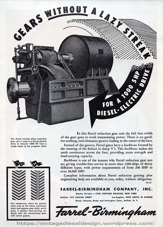
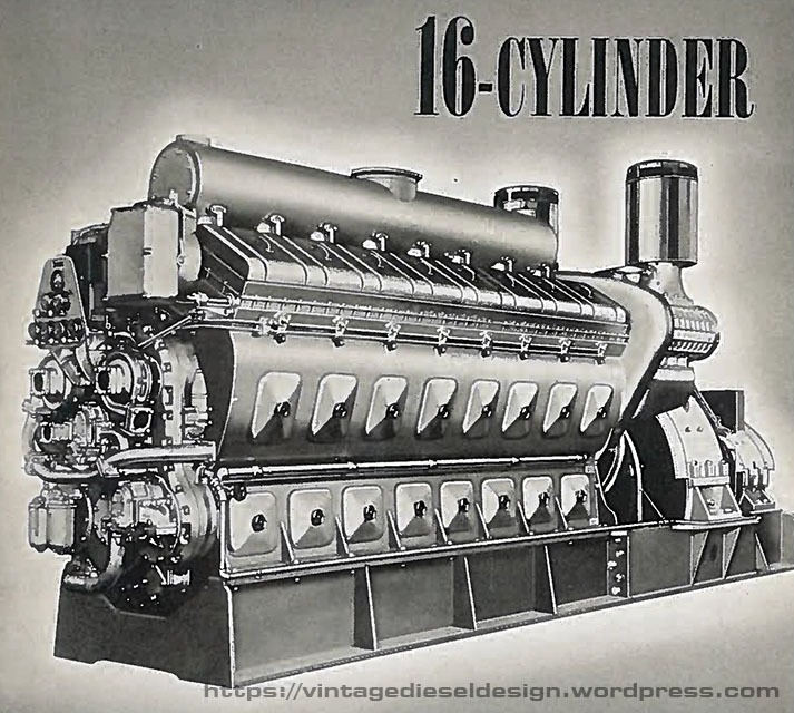
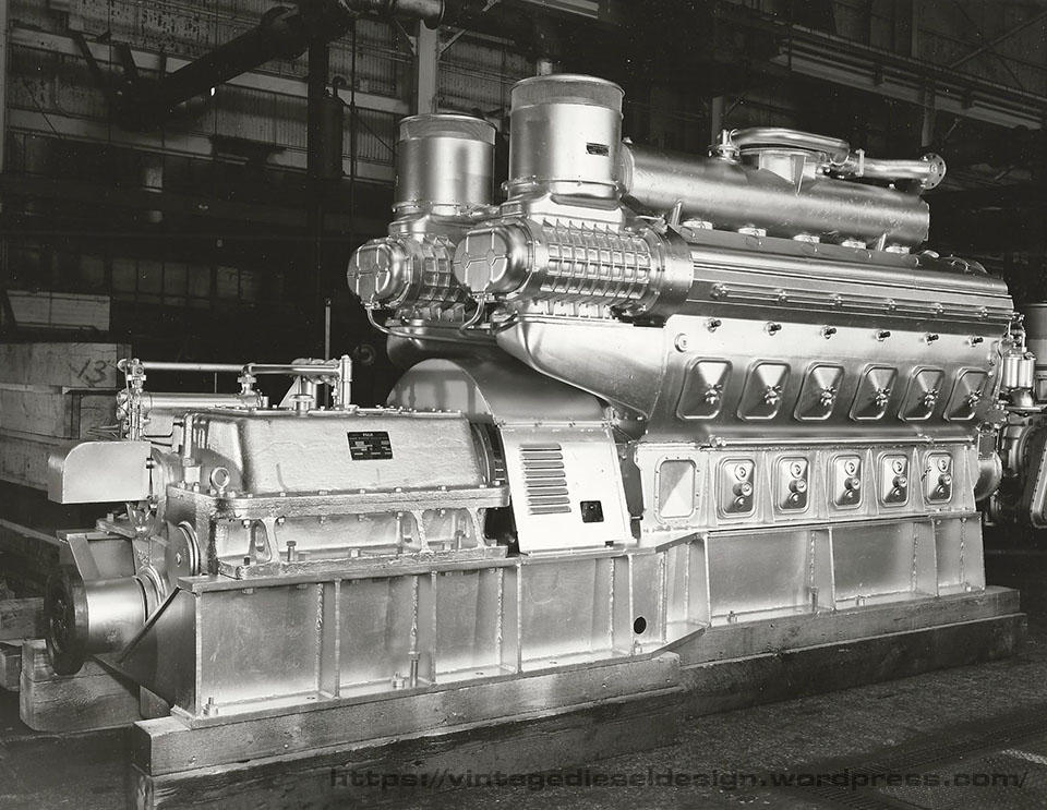
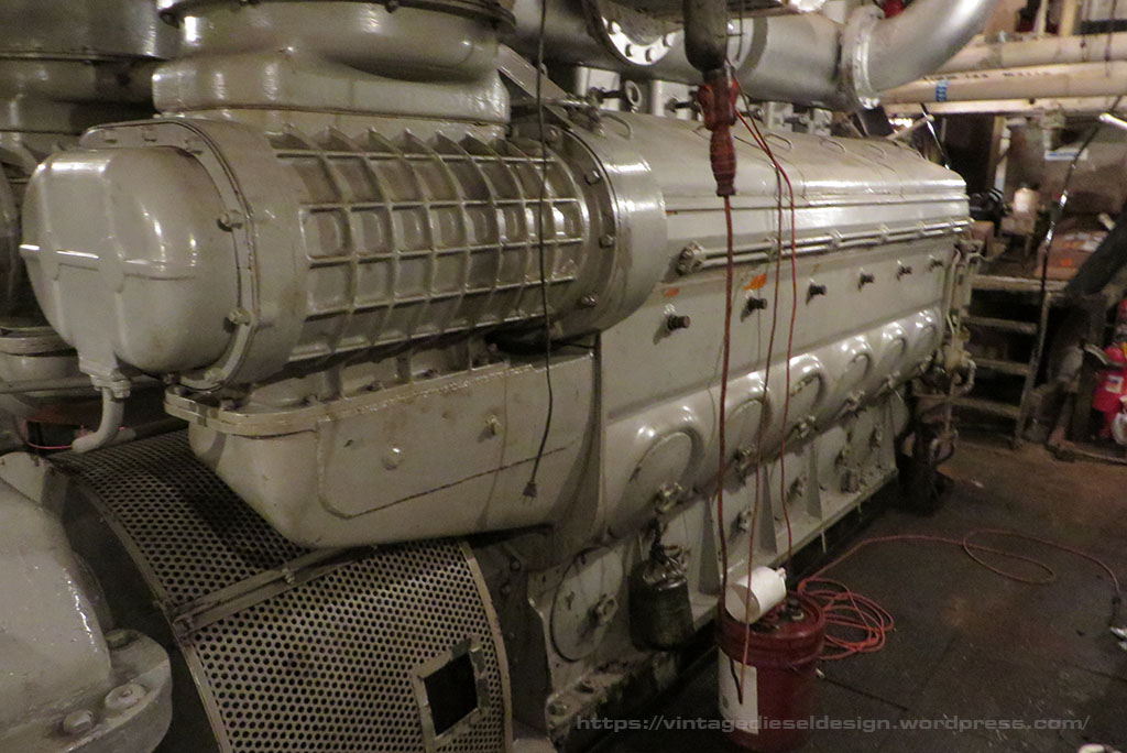
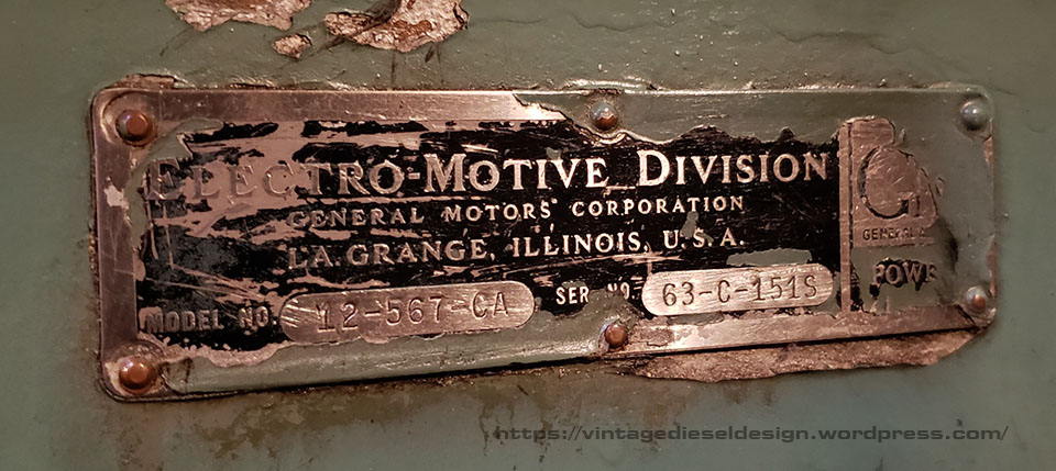
Ill start with a bit of prequel to this story with some history.   The Tug Cornell is powered by a Cleveland Diesel “Navy Propulsion Package”, which consists of a Cleveland 16-278A and an Allis Chalmers 1090kW, 525V DC Generator, mounted on a common base.   In turn, this provides power for a Westinghouse 1350HP electric propulsion motor, driving a Farrel-Birmingham single reduction gear.   Except for the gear, all this equipment is reconditioned WWII surplus, Destroyer-Escort equipment.   Lots more to come on this equipment in a future post. 

Both ends of the main generator, as well as the forward end of the propulsion motor are supported by large, oil fed babbit pedestal bearings.    The generator ones are fed by the main engine lube oil system, and the propulsion motor one is fed off the reduction gear oil system. The motor only has a single support bearing on the front, as the rear is supported by the reduction gear.   In April of 2012, we burned up the aft support bearing on the generator; however, I will save that for later, as I documented this instance better.

Destroyer Escort propulsion motors, were used in pairs on the ship. When resold for commercial service, they were split into single units.

In September of 2015, on a Sunday afternoon, we were just leaving with the tug to head down river, with another small tug (Pilot, Dave’s tug) alongside. The plan was to drop off the Pilot in Verplank, head to the city to pick up a barge, and then back to Kingston as we had training class days later in the week in Kingston.  About 45 minutes out, just at the Esopus Meadows light just South of Kingston, I go down and do my engine room checks.  I have my routine, I go down the stairs, around the front, back, around, back to the gear, and back up…so, coming around the front, I smell burning.  The best way I can describe it is a burning electrical smell.  I remembered the smell from when we burnt up the generator bearing.  So, I kind of figured it was THAT bearing acting up again, I run around back looking for the thermal gun, and in the process put my hand on top of the motor bearing (part of my routine..), and yeah, at that point I knew what was really happening! 

So, I get on the horn to the wheelhouse (we have a radio from the engine room to the wheelhouse) to go all stop, GET THE PILOT RUNNING!, and GET DOWN HERE!, I run for the hose to start getting water on the thing. (270 degrees on the shell right now).  Dave starts steering, Don runs over and gets Pilot running (This is after we drained the fuel tanks this week, leaving only 50 gallons on the day tank…) Matt runs down and helps me start cooling this thing down with just water and rags.  By now, we are just hanging out in one of the wider parts of the river.  Pilot is running and ready to go alongside and holding us.  Me and Don start tearing the oil lines apart to the bearing.  We put air to it, and it shot a solid slug of crap out…  

  Now, the forward support bearing, is pressure fed from the reduction gear.  Its a very simple system.  There is a suction line from the sump of the reduction gear with a check valve, this goes to the pump driven off the main pinion.  From the pump, it goes through a cooler, strainer, then T’s off.  One line goes up to the support bearing on the motor, and the other goes to the gearbox, for the top spray line, and the pinion and thrust bearings (which are SKF ROLLER BEARINGS!) in the gearbox.  All the oil is crystal clear and looks fine.  it was just that one slug of shit, in the lowest part of the system.  The system is only supposed to run at 110 degrees, at 5-8 psi. 

So, we get this thing cleaned out, Pilot is holding us so we don’t drift all over the place ( Dave’s friend managed to see this from shore!) we get it back together, but we can’t get the pump on the gearbox to reprime quick enough to cool the bearing and get some oil to it.  We thought we might have caught it before it went nuclear, but when we turned the excitation on (When you turn it on, the motor creeps sometimes), we got the nail on chalkboard sound

Ok, Time to have Pilot turn us around, and tow us back to the dock. Nothing we are going to do out here now. 

Click for larger.

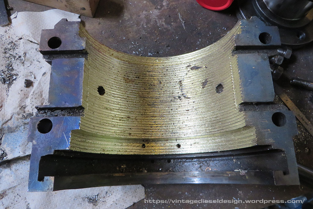
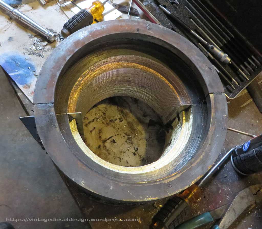
With the upper half of the pedestal removed, and the upper shell removed we saw the damage was done. All of the babbit melted out and then reset when it cooled off. What looks like scoring on the armature shaft, is actually just streaks of babbit.

Upper half of the shell. Click for larger.
Lower half of the shell. Click for larger.
Both halves of the bearing. Click for larger.
Both halves of the bearing shell. Click for larger.
Click for larger.

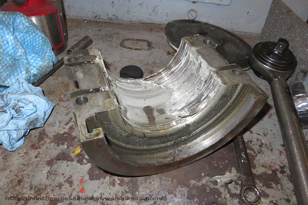
In removing the lower half of the shell, we made the observation that this has happened once before. Notice on the upper lip where it has been built up with brazing from where the shaft dropped and wore out the shell. Note the two oil drain holes in the center. Also, note the heat distortion. This shell got to over 500 degrees to melt that babbit in that fashion. Luckily, the shell was not warped.

So, a few years ago our fellow engineer friend Tim Ivory built a centrifugal bearing machine, to re-pour the main bearings in the tug “Spooky Boat”s Fairbanks-Morse 35F10M engine.   Well, it turned out we were the first to make use of it two years prior when we cooked that generator support bearing.   Since then Tim has made several bearings for various projects. 

  The barge in the city can wait until next week, but the class days Wednesday, Thursday and Friday can’t be rescheduled.  Sunday night we got the shell apart.  It is only 4 cap bolts, 4 shell bolts, and a pipe fitting into the shell for the oil line.  After we got the motor armature shaft supported, the lower shell just spins out. 

We were not able to do anything Sunday night.  It turned out, Tim already had the bearing machine off the storage rack, and had one of the small, 2″ bearings for Spooky boats 1 Cylinder FM generator mounted in it to re do.  We took care of that on Sunday to get it out of the way.  

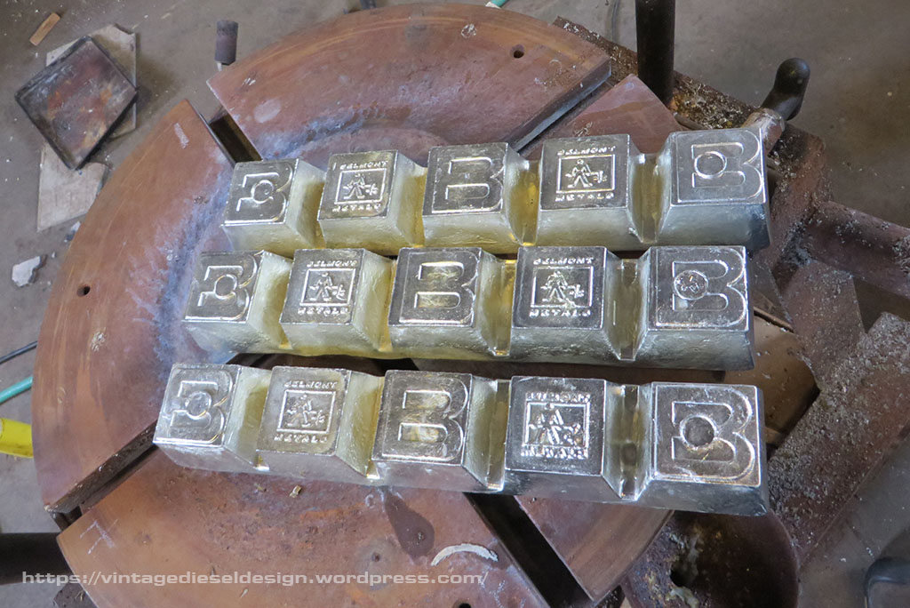
Monday, Matt (Owner of Cornell), had to go to the city and take care of a few things.  Great, we found a foundry down there that has the babbitt in stock (Belmont Metals), and we can pick it up.  Next, we need gaskets, The bearing mounts to the table using 4 studs and a plate.  The shell needs a gasket where it meets the mounting plate, or the hot liquid babbitt just pours out all over.  It is a 4″, ring style flange gasket, rated for hi-temp, usually graphite based, 1/8th” thick. We can’t source them locally.  I found a place in Brooklyn that has them, I call them, tell them exactly what I need. Ok, fine no problem, 6 in stock.  While this is going on, we prep the shell.  Simply, melting the old babbitt out.  

Melting out the babbit using a roofing torch. Click for larger.
The shell, now cleaned of all old babbit and tinned. Click for larger.

The next issue at hand was that we needed a plug. On the after side of the bearing, the outer edge of the shell rides on the larger portion of the shaft forming a mechanical oil seal. Unlike the bearing on the generator which used a labyrinth cut into the babbit, this bearing just have a tight tolerance fit, and thus we need to keep this entire area clear of any babbit. Tim had the great idea to make a simple one out of the bottom of an old scuba tank!

Making the lower plug from a scuba tank. Click for larger.
Click for larger.

After the bearing is cleaned out and tinned, the halves are bolted together with an aluminum shim plate, which is sealed with hi-temp silicone. The shims create a space so that the shell can be split apart after the babbit is cooled, and the babbit wont stick to the aluminum.

The rear plug is centered up in the rear. Click for larger.
New 6lb ingots of babbit from Belmont Metals, in Brooklyn. The babbit consists of 78% Lead, 14% Antimony and 8% Tin. Click for larger.

Now, Matt shows up with the gaskets Monday afternoon…totally wrong thing.  Back to the drawing board.  I managed to find a plumbing supply house about an hour away.  We shoot down, and start telling them what we need, and comes the typical “What is the application..”  Our response, “Can you just take us to where you keep them, and we will get what we need?”  They take us to them, score! they had what we needed.  

Click for larger.

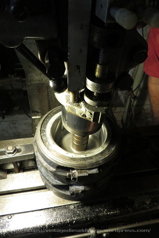
The shell itself is sandwiched into the machine using 4 studs attached to the bed plate, and a steel plate with the center cut out. After a few minutes getting the bearing centered and balanced, it is ready to go. Each of the 4 studs is wrapped in fiberglass insulation to help prevent the stud from stretching, and have stiff springs outside of the plate to take up and stretch while being heated, and even still they are periodically re-tightened. The gasket sits between the top plate and the shell.

Click for larger.

Next up, rotating the assembly down 90 degrees and preheating the bearing using the roofing torch to around 500 degrees. In the background the babbit is being melted.

In goes the babbit. Click for larger.
Click for larger.

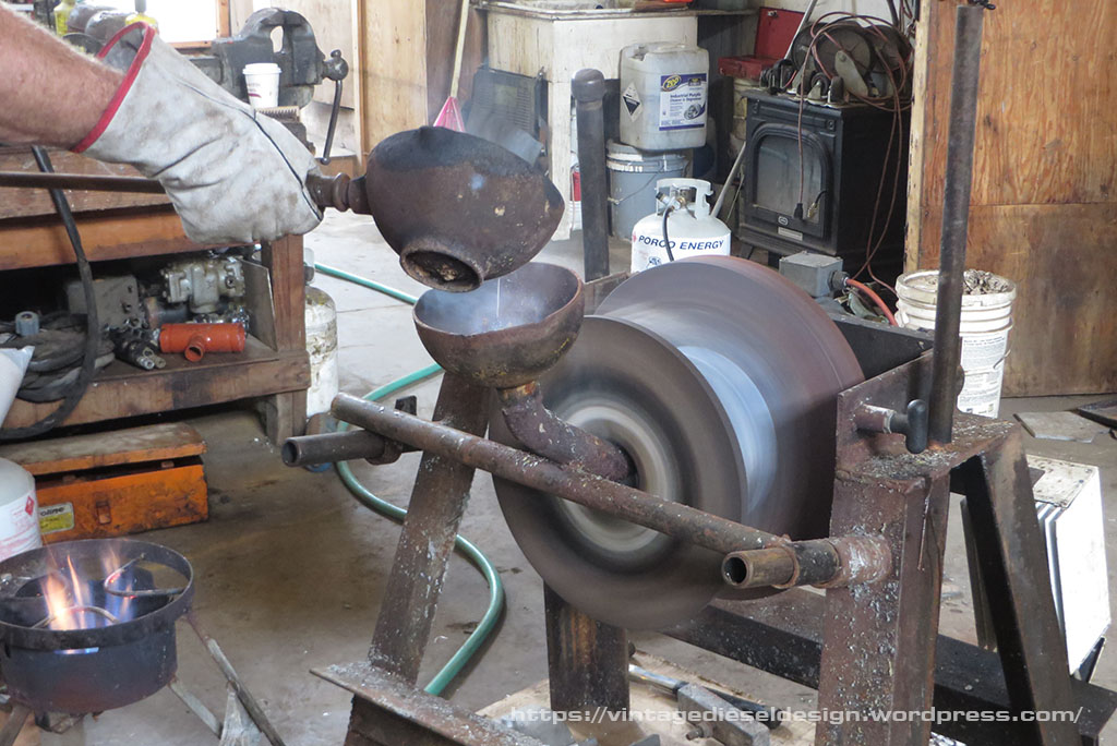
We melted 12 pounds of babbit and poured in about 9. After pouring, the shell is immediately hit with water to cool it. This is so the shell cools and shrinks from the outside, so the babbit does not crack.

This is how the bearing looks directly after pulling off the outer cover plate. The green is the remnant of the gasket. Click for larger.
The bearing after being split apart. It can now be bolted back together without the shims, and be machined. Click for larger.
Click for larger.

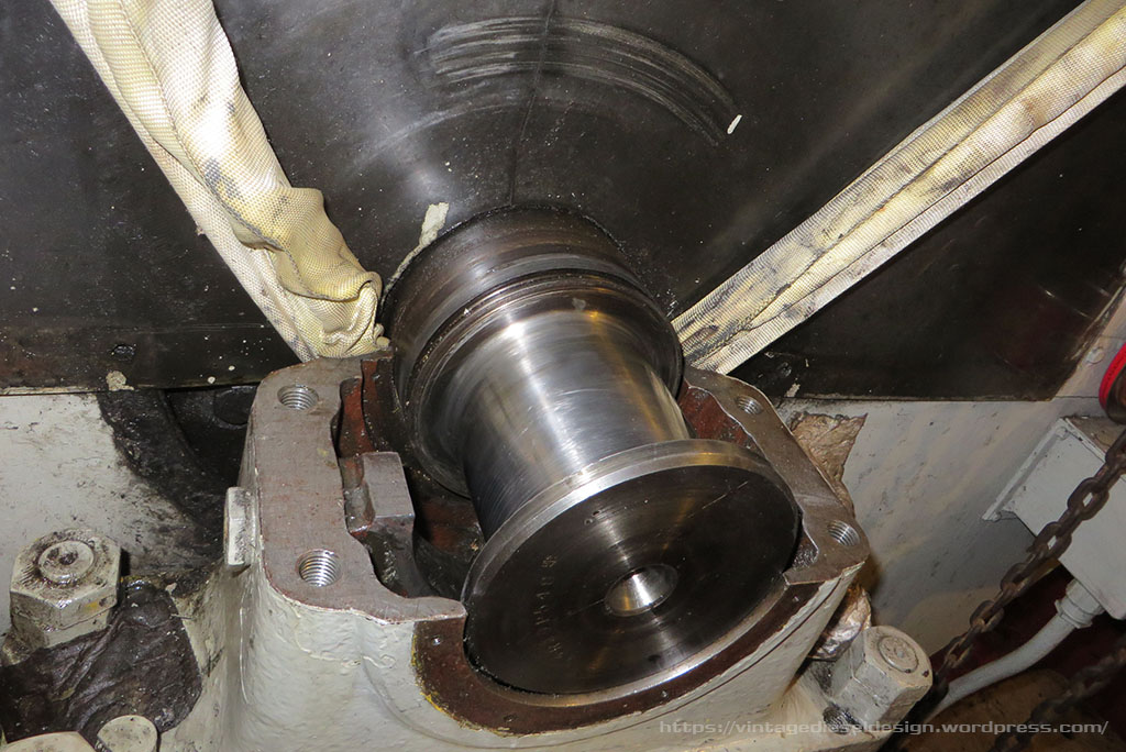
With the new babbit poured, we went back and cleaned up the shaft. It had some very, very light scoring on it that we were able to polish out. We took a slew of measurements, and were now ready to machine it.

Mounted in the lathe and cut to final size. Click for larger.
Cutting the oil wedge’s out on the milling machine. Click for larger.
The finished bearing shells. Click for larger.
The propulsion motor, with the shaft supported from the overhead using a chain fall and sling. Click for larger.
Rolling in the lower bearing shell. Click for larger.

We put the thing back together about 11pm on Tuesday, figured out how to get the oil pump reprimed, cleaned all the lines out, and started the boat about 11:15.  We spent the next hour running it, getting it scrapped in with a razor blade and bluing dye (run for 25m, take it out, scrape…repeat..).  We used timesaver compound (an old timers trick for babbitt bearings, which alot of old manuals for big engines specifically say to use for this exact purpose), to help get it wore in.  

The class days we took it easy, no more then 100 shaft rpm (so about 400 on the motor).  We never seen more then 100 degrees on it.  Here we are almost 4 years later, and the bearing runs perfectly fine, and stays right around that 110 degree mark. For all intensive purposes, we were able to turn this repair around in around 48 hours, completely in house.

Since this happened, not only have we managed to acquire a spare support bearing shell set, but I even managed to find an original Cleveland issue manual, that covered the Generators, Motor and the pedestal bearings for both, with complete spec sheets.

Cleveland Diesel manual covering the Destroyer Escort’s propulsion end.
Blueprint sheet for the forward support pedestal bearings. Click for a larger version.

Old Advertising IV

Click for larger

Farrel-Birmingham was yet another prominent WWII (and before) era manufacturer of reduction gears and the like. During WWII, Farrel-Birmingham would supply gears for hundreds of tugs, ships, ferrys and every many other pieces of floating plant. In the post war years, working with GM, thy would supply the reduction gears for almost every Diesel Electric tug powered by Cleveland Diesel right up until the 1960’s.

The setup shown above was originally used in the tug “Raymond Card”, a 95′ tug powered by a Cleveland 12-567, with a 615kW Generator. In turn, this powered the 750HP 600V DC propulsion motor, that fed the Farrel-Birmingham 3.75:1 reduction gear. This same setup would be used on other tugs of the same design later on.

Farrel-Birmingham would exit the gear market in the 1960’s. They still exist today as the Farrell Pomini company, specializing in plastic manufacturing equipment.

EMD 567 Spotters Guide

Something that I see quite often on various forums and the like, is misidentification of the early EMD 567 series engines.  Like all engine manufactures of the day, the EMD 567 line was under constant revision throughout the years.  This is not meant to be any sort of history of the engine,  just a simple way to differentiate the different types of 567 engines. 

The “Straight” 567

One of the first EMC 567’s built in July of 1938 for the “Thomas E. Moran”. While the base engine was built by EMC, it was then sent to Cleveland Diesel to be converted into a marine engine. Note that while the rectangular crankcase and airbox covers are the same, the crankcase ones are horizontal, while the airbox ones are vertical. These engines would be removed and replaced with a single 12-278A in 1944.

The first production model of the 567 was just that, the 567. Often people dont associate this engine, thinking the 567A was the original, but it was not. The first 567 engines used an interesting top deck design, with extended crab studs to hold down the covers, with a simple rectangular hatch over each injector. The first pair of production 567’s according to the EMD book “Diesel War Power”, were for the Moran Towing “Thomas E. Moran”, built by Defoe Shipbuilding in 1938. Ironically, an engine designed specifically for locomotives, would be first installed in a tug. The engines (one pictured above) were V8, 660HP/750 RPM engines that drove a 400kW generator, with a 24kW belt drive exciter above.

A spare 12-567 on a flat car at the Illinois Railway Museum

The first Railroad use of the 567 would follow in October of 1938, with a set of E4 Streamliners for the Seaboard Air Line railroad. Each E4 used a pair of 1000HP 12-567’s. The first and most obvious way to spot the straight 567, is the very wide housing for the blower drive gears, making the rear end of the engine rather wide. EMC/Cleveland would supply special versions of this engine to the USCG for use in a fleet of Icebreaking Tugs, with a narrowed version of this case, however all of the standard production engines used this wide case. By now, the engine also featured matching doors on both the crankcase and airbox, as well as a larger, removable cover that spanned the entire top deck.

Click for a larger version

Note the upper deck of the engine in the “U” (cast) or “V” (fabricated) upper portion where the exhaust coming out of the heads would mate up with the upper manifolds. The original EMC 567 design is well outlined in Eugene Kettering’s paper on the History and Development of the 567, which will be linked to at the end of this article.

The production EMC 567 would be offered in 6, 8, 12 and 16 cylinder models

567A

With the onset of WWII, the 567 by now was being refined into the 567A starting around 1942. What would put the 567 line on the map, would be the advent of the Navy LST program. The majority of the LST program would in turn use a pair of 12-567A engines (dubbed ATLP/ATLS for Aux. Tank Landing Port or Starboard), driving a 2.48:1 reduction gear through an air clutch. On land the 567A was being used in all of EMD’s line of locomotives from switchers to road power.

Click for a larger version

The 567A would take the idea of the narrowed blower drive on the USCG 8-567’s, and make it even narrower, thus saving crucial space in the engine room. Midway through the LST program in 1943, the two piece floating piston and carrier design was adopted. Also to note, is the entire upper deck was modified, and now the exhaust from the heads ran inside of a water deck. Note the smooth cast ducts for the scavenging air from the blowers into the airbox.

An early Cleveland 12-567A with a Falk clutch/gear drive. J. Boggess Collection.

The 567A package used in the LST would go on to be one of the most common repower package for tugboats in the 1950’s and 60’s, something we will get into more in the future.

567B

The 567B was introduced after the end of WWII. The 567B was very similar to the 567A, with one main spotting difference on the outside. The 567B now used a ribbed air duct casting from the blowers into the airbox.

Mechanically the 567B was essentially the same as the 567A, with the difference being the attached oil strainer housing on the front end of the engine.

567C

In 1953, EMD introduced the 567C. The C block engine was essentially an all new engine. The C blocks major change involved the elimination of the water deck liners, and the use of O rings to seal them. These O rings were prone to fail, and would thus cause water contamination of the lube oil system. The C liners used a bolted on water inlet type, completely eliminating the water deck.

A Cleveland 16-567C with a Falk 16MB reverse reduction gear. This was one of the more popular marine uses of the engine through the 1960’s. J. Boggess Collection.

The easiest way to spot a 567C – is that the block introduced a few new changes. First is the round inspection covers on both the airbox and crankcase. The fuel rails were moved to the inside of the upper deck, as well as an all new style of hinged upper deck cover, with snap latches. The thing about the 567C is that it is also identical to its replacement, the 645 series.

Click for a larger version

567CR

A short one here – the 567CR was only an 8 cylinder engine, that used a revised firing order, hence the “R”, to help with vibration issues. Externally it is exactly the same.

567D

The final installment in the 567 lifespan development is the 567D of 1959. The D line of engines introduced the turbocharger. EMD, unlike Detroit and Cleveland would develop their own turbo, that was driven off of the gear train through a clutch at low speeds, and would freewheel when the exhaust pressure built up. The 567D was only offered as a 16 cylinder engine, and topped out at 2500HP. Later on they would take the turbo off for a few select applications, and squeezed 1800HP out of it. The 567D2 (used in the GP20 locomotive) utilized a slightly different turbo design, with straighter appearing ducts into the airbox.

The turbo versions of the 567D while overall successful engines and were a major stepping stone to the 645 development, however were plagued with turbo issues early on. Several railroads choose to pull the turbos off and replace them with the traditional roots blowers.

567AC and 567BC

The AC and BC engines, from the outside are identical to their original counterpart. Internally, the engines were upgraded to use “C” block liners (but kept the A/B heads). The only way to spot one of these, would be to remove an airbox cover and see if the water manifold is present.

567CA

Not to be confused with the above conversions, the 567CA engine is its own beast. While it was not any sort of a new development, the CA engine was an EMD designed direct replacement for the 567ATL LST engines that by now were in hundreds of commercial boats.

12-567CA in the tugboat “Jupiter”

The CA engine used a new crankcase with “C” specs (including liners as well as cylinder heads), however there were several recycled parts off of the original ATL engines. The smooth blower ducts, as well as the entire top deck assembly, complete with the external fuel lines and removable covers were recycled off the original engines.

The 12-567CA engines were developed in the early 1960’s as drop in replacements.

645C

Yes – the 645C is actually a 567. The 645C is a 567C that uses 645 power assembly’s. Again, like the AC and BC conversions, the 645C is not distinguishable from the outside. These are sometimes known as a 567E. 

Wrap up…

Please note, I wrote this simple as a way to try and help to visually distinguish each model of 567. One thing to keep in mind, is the 567 was a very modular engine at the end of the day, and quite a few components are interchangeable throughout the entire production line, some easier then others.

As mentioned previously, the 567 was an EMC/EMD design, and was built in the LaGrange shop. Between 1938 and 1961, both marine and stationary versions of of the 567’s were marketed and sold under the Cleveland Diesel banner, having been converted for such uses in their Cleveland shops. These engines carry Cleveland Diesel builders plates, and numbers.

Preston Cook, one of the leading authority on EMD, has a fantastic write up at the following link which gets a bit more into the technical sides of the model development over the production spans.

Preston Cook – EMD 567 in the 21st Century

Eugene Kettering’s paper “History and Development of the 567 Series General Motors Locomotive Engine” hosted over at Utah Rails.