Several years ago, we were doing a gasket kit on a power pack on the Cornell. We had it torn almost all the way apart and I had a “brilliant” idea… Lets see whats in the exhaust.
So… I reach in….expecting some carbon chunks..
Huh..there’s a pile of something… I don’t think its carbon.. Its just this one pile..
There’s a lot. Huh. Lets see if I can get it out.
What the hell!
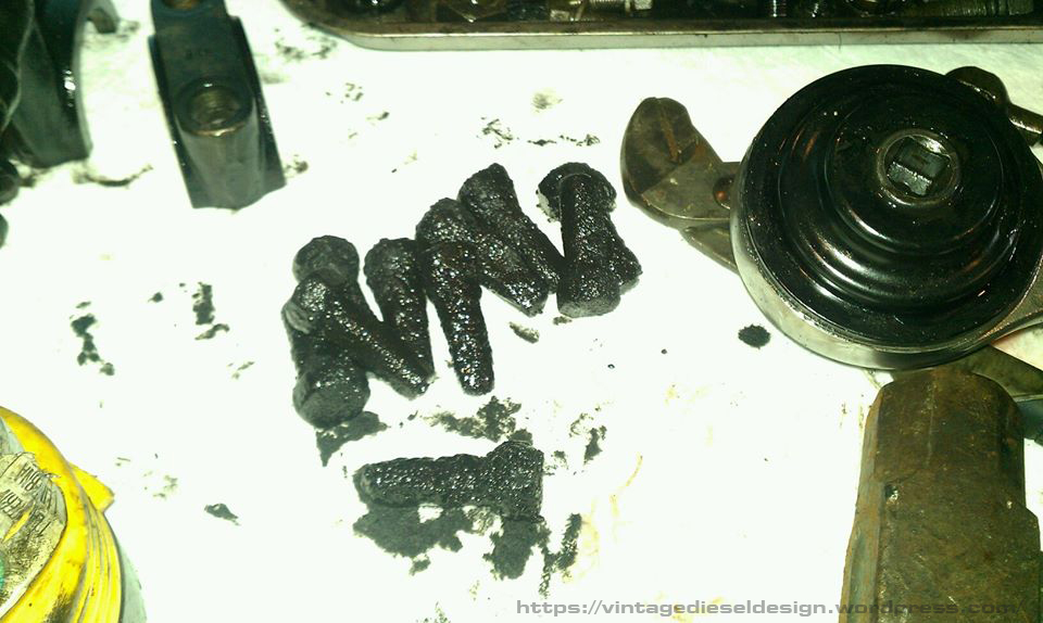
Click for larger.
Sure as shit, it was a pile of bolts. They were totally caked into the oil and carbon in the bottom of the manifold. Turns out – Once upon a time, somebody doing the same thing many years ago, must have pulled the exhaust jumper off, and stuck the bolts in the manifold so they don’t get lost. Because that seems like a great idea..
The exhaust jumper is held on with 12 bolts, 6 on top and 6 on the bottom. The kicker is the top ones are fine thread, but the bottom is coarse thread, so you cant mix them. In-between is a set of asbestos-copper gaskets between the elbow and the head/manifold.
We did not feel the need to put them back in.
A look into the manifold. Not bad considering the engine does not get worked hard at all. Click for larger.
Its been a busy holiday season. Hopefully I can get back on track soon with a weekly advertisement as well as getting some more in depth write ups done.
Seeking out leaking liner O rings. The Cleveland 278A uses a water deck style liner, somewhat like the early EMD’s. Yes, that is a piston by the stairs. Makes a great step stool. Click for larger.
In 1948, the Lehigh Valley Railroad put in an order for a quartet of tugboats. The tugs, designed by TAMS Inc. Naval Architects under Richard Cook and Joseph Hack, were a typical 106’ harbor tug. I will get into this more in a future topic (or whenever I get my damn book finished!). The Diesel-Electric tugs were powered through a package put together by General Motors Diesel – Cleveland Diesel main engine, Detroit Diesel generators, Allis-Chalmers main generator, Westinghouse propulsion motor, and electrical gear provided by Lakeshore Electric. Construction of the tugs began in early 1949 at Jakobson Shipyard in Oyster Bay, Long Island. The tugs would be named the “Wilkes-Barre”, “Hazleton”, “Cornell”, and “Lehigh”. The 4 tugs were identical, with the exception that “Cornell” and “Lehigh” had wheelhouses slightly lower than the other pair for serving the isolated terminals on the Harlem River.
The tugs were powered by the typical Cleveland Diesel Navy Propulsion Package. A 16-278A engine, rated at 1655HP driving an Allis-Chalmers 1090kW DC generator, mounted on a common base. In turn, this powered a Westinghouse 1380HP propulsion motor, driving a 10’ propeller through a Farrel-Birmingham 4.132:1 reduction gear. At the time, WWII surplus equipment was vast. Cleveland Diesel was acquiring little used engines from various craft and giving them a complete rebuild to as new condition, complete with new serial numbers. The main generators and propulsion motors were both surplus Destroyer-Escort surplus equipment as well.
“Cornell” was launched on April 4th, 1950. After launching, diver Edward Christiansen went down to remove launching timbers. One of the large pieces of wood broke and not only pinned him against the tug, but also pinched off his airline. His son Norman led a rescue effort, and in 21 minutes were able to get him back up to the surface after using a yard crane to roll the tug slightly. Once on the surface, firefighters were able to revive Edward, and he was taken to the hospital.
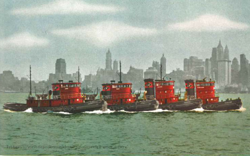
The “Four Aces” was a publicity photo arranged by Cleveland Diesel. This was used, both colorized and Black & White, in several publications of the era.
Cleveland Diesel order #5782 consisted of the following engines:
“Wilkes Barre”– Original engine #55341, installed in US Navy “LSM-277”, shipped 9/5/1944. Engine removed upon decommissioning, factory rebuilt, and assigned new engine #55944 upon being shipped 5/13/1949 for use by LV.
“Hazleton”– Original engine #55342, installed in US Navy “LSM-277”, shipped 9/5/1944. Engine removed upon decommissioning, factory rebuilt, and assigned new engine #55945 upon being shipped 5/13/1949 for use by LV.
“Cornell”– Original engine #12001, installed in US Navy DE-526 “Inman”, shipped 10/15/1943. Engine removed upon decommissioning, factory rebuilt, and assigned new engine #55946 upon being shipped 8/29/1949 for use by LV. This engine was replaced 12/1950 with factory rebuilt engine #55956 (engine only, less base & generator, shipped 12/15/1950), originally from “LSM-184”, engine #55347, shipped 9/7/1944.
“Lehigh”– Original engine #55654, installed in US Navy “LSM-436”, shipped 1/23/1945. Engine removed upon decommissioning, factory rebuilt, and assigned new engine #55946 upon being shipped 3/21/1950 for use by LV. In the early 1990s, while owned by Moran Towing, the “Lehigh” (then called “Swan Point”) received the engine from the scrapped NY Cross Harbor tug “Brooklyn III”, the former New Haven tug “Cordelia”, which was a WWII surplus engine like all of the rest, originally in Navy DE-259 “William C. Miller”, which is ironic, as the Bethlehem below, also received one of her engines.
Lehigh Valley would return in 1951/53 for two more tugs of the same design, with some slight differences. These tugs were powered by the same propulsion package, of WWII surplus equipment.
Cleveland Diesel order #8112:
“Capmoore”– Original engine #11734, installed in US Navy DE-259 “Wm. C. Miller” , shipped 5/1/1943. Engine removed upon decommissioning, factory rebuilt, and assigned new engine #55964 upon being shipped 4/19/1951 for use by LV.
Cleveland Diesel order #314
“Bethlehem”– Original engine #11736, installed in US Navy DE-259 “Wm. C. Miller”, shipped 5/1/1943. Engine removed upon decommissioning, factory rebuilt, and assigned new engine #55966 upon being sold for commercial use. Original order canceled, reassigned engine #55991 upon being shipped 5/8/1953 for use by LV. “Bethlehem” was re-powered by an Alco 16-251 in the early 1990s, and is the only other surviving LVRR tug, now working in Guyana.
Naturally, with the downfall of the railroads maritime traffic, the railroad would start selling the tugs off starting in the early 1960s. “Cornell” would last until 1970, with Bethlehem being the final LV tug, sold off in 1976. As noted above, for an unknown reason, the engine in the “Cornell” failed almost immediately after delivery and the bare engine (no base or generator) was replaced by Cleveland.
————————————————————–
The US Fleet Tug “USS Cabezon” – SS 334, slid down the ways of Electric Boat in Groton, CT on August 27th, 1944, sponsored by Mrs. T. Ross Cooley. “Cabezon” was on the tail end of WWII sub construction, specifically part of the 120 boat Balao class. Construction started with her keel laying on November 18th, 1943. She was placed into service on December 30th, 1944, and after training went on to Pearl Harbor in April of 1945, under the command of George W. Lautrup Jr., making this his 10 WWII patrol.
Launching of the fleet sub “Cabezon” at Electric Boat. USN photo # 80-G-448206 from National Archives and Records Administration (NARA), College Park, Maryland, courtesy of Sean Hert via Navsouce.org. Click for Larger.
“Cabezon” was powered by 4 Cleveland Diesel, 1600HP 16-278A engines, driving 4 GE 1100kW DC generators, with 4 GE 1375HP propulsion motors, rated for 5400HP on the surface and 2740 submerged. She had a single Cleveland 8-268A 300kW auxiliary diesel, and 256 Exide VLA47B battery’s.
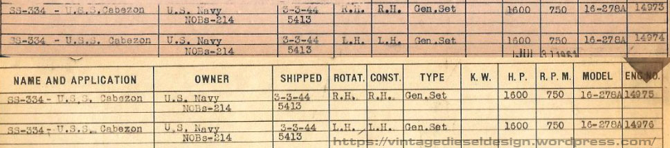
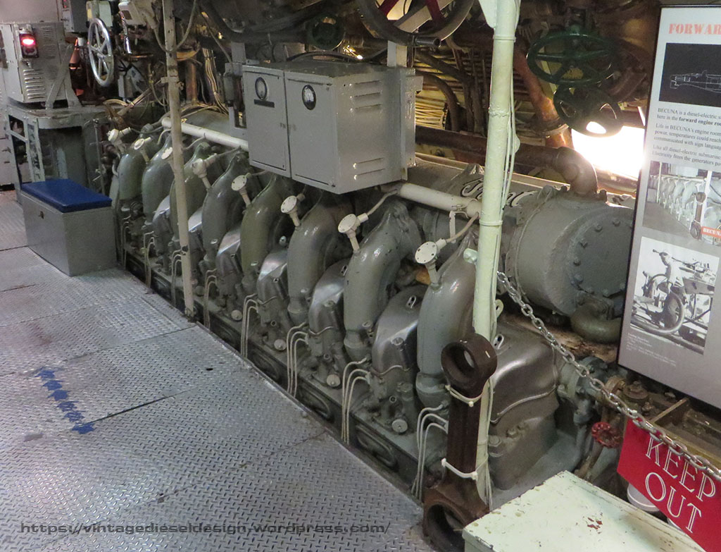
Order sheets for the 4 main engines in the sub “Cabezon”, part of navy order NOBs 214/CDED 5413. J.S. Boggess Collection. Click for larger.Cleveland 16-278A located in the sub “Becuna”, SS-319. “Becuna” is one of the sisters of “Cabezon”. Click for larger.
After arriving in Pearl, “Cabezon’s” crew underwent more training. During which an accident occurred. The 4 outer rear torpedo tube doors were opened, while 2 of the inner doors were open. The sub immediately began to flood. Reid Harrison Peach Jr., TM1c, William Cliffard Markland, TM1c and Brownie Walter Szozygiel, TM1c were each awarded the Navy Marine Corps medal for their action in saving the sub.
An interested experiement conducted by the “Cabezon” early into her first patrol. From “Cabezon’s” War Patrol Report. Click for larger.
“Cabezon” went on her first WWII patrol starting May 25th, 1945, in the Okhotsk Sea and Kurile Islands, operating in attack task group 17.15 with subs “USS Apogon”, “USS Dace” and “USS Manta”. “Cabezon’s” war patrol report is fairly tame, being so late into the war. On June 1st, they spotted a floating mine, which they sunk with the .50 caliber machine gun. A second was spotted June 6th, which exploded after they hit it with the .50 cal. On June 18th, “Apogon” made contact with a Japanese convoy, attacked and sunk 3 ships by midnight. At 0130, another contact was made, in range of “Cabezon”. After 30 minutes of pursuit, she launched 3 Mk. 18-2 torpedoes from 2250 yards. Two hits were observed from the bridge, as well as 3 timed explosions, and the contact was reported sinking at 0223. June 29th – Another contact made at 2145, lasting until 0025, when it was discovered a shorting out heater was the cause. “Cabezon’s” war patrol ended July 10th, when she arrived at Midway.
“Cabezon” would be credited with sinking one unidentified Japanese escort (Later identified as the “Zaosan Maru”), rated at 4000 tons. 103,485 gallons of fuel were used during the trip, which covered 10,275 miles. She had 21 torpedoes, 32,510 gallons of fuel and provisions left for 15 days. “Cabezon” went on to Pearl for her refit period and left for Saipan on August 4th. Hours before leaving for her 2nd patrol, WWII ended. “Cabezon” stayed in the area, providing targeting practice for surface ships, before leaving for the Philippine Islands in early September to become part of the new Submarine Squadron 5, with subs “USS Chub”, “USS Brill”, “USS Bugara”, “USS Bumper”, “USS Sea Dog”, “USS Sea Devil” and “USS Sea Fox”. In December, Squadron 5 returned to Manilla, and joined up with the “USS Chanticleer” and Destroyer Escorts “Earl K. Olsen” and “Slater” (Now a fantastic museum ship in Albany) for training exercises. “Cabezon” would go on to do a short stint in San Diego, and later Pearl Harbor, doing trips for the Naval Reserve. In 1947, she took part in Operation Blue Nose, exploring under the Polar Ice Caps along with subs “USS Boarfish”, “USS Caiman” and tender “USS USS Nereus”. “Cabezons” final trips would be in two reconnaissance patrols, one in March-July of 1950, and the 2nd April-October of 1952 between Hokkaido Japan, and Sakhalin, USSR.
“Cabezon” would set out for Mare Island in April of 1953 where she was laid up in the Pacific Reserve Fleet. She was recommissioned in April of 1960 as a Naval Reserve Training boat in Tacoma Washington, and reclassed in 1962 as an Auxiliary Research Submarine, until being decommissioned in 1970. She was struck from the roster on May 15th, 1970, and sold for scrap to Zidell Explorations, of Portland Oregon in December of 1971, for $69,230.
While on Patrol, “Cabezon” had a unique engine failure, as outlined in her war patrol report below. #4 main engine, is one of the Portside engines on the sub, on the after end (#2 and #4 are Port, #1 and #3 Starboard). The port engines are both left hand rotation engines.
From “Cabezon’s” War Patrol Report. Click for larger.
————————————————————–
In 1970, Lehigh Valley sold the tug to Ross Towboat, of Boston Massachusetts, keeping her original name in the process. Ross was actively engaged in Ship Docking, as well as barge towing in Boston, as well as all New England. Ross would do some slight modifications to the tug, including adding an internal staircase to access the pilothouse, as well as add a full galley and staterooms to have a full-time crew on board, whereas the tug did only 8-hour day work for LVRR. In early 1972 the tug had a catastrophic main engine failure. Thanks to my friend Douglas Della Porta of Eastern Towboat, he recounted the story of what happened.
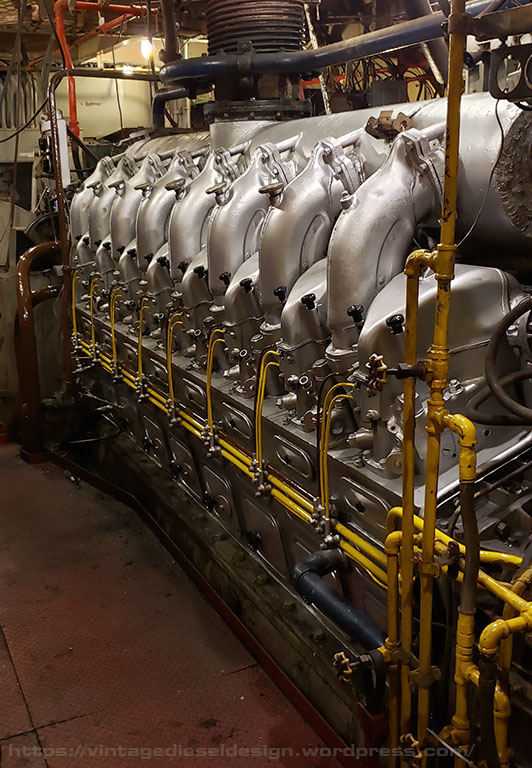
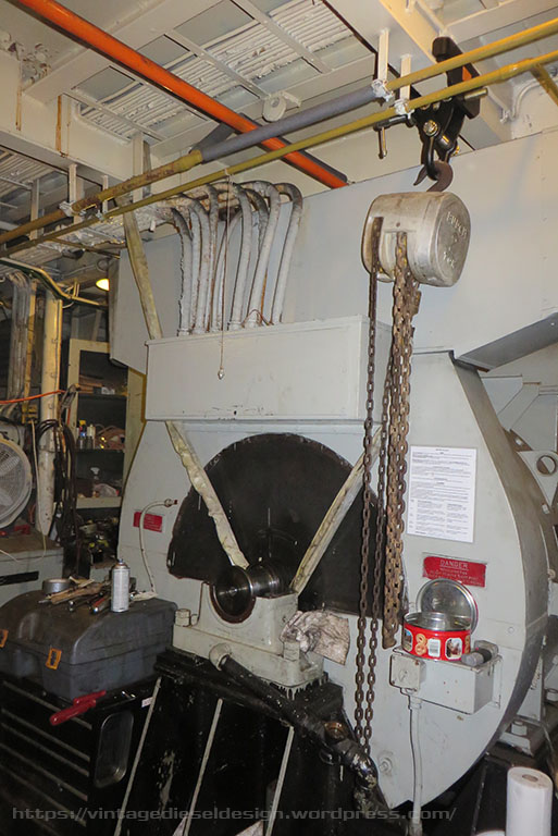
Port side of the main engine in the tug “Cornell”. Click for larger.
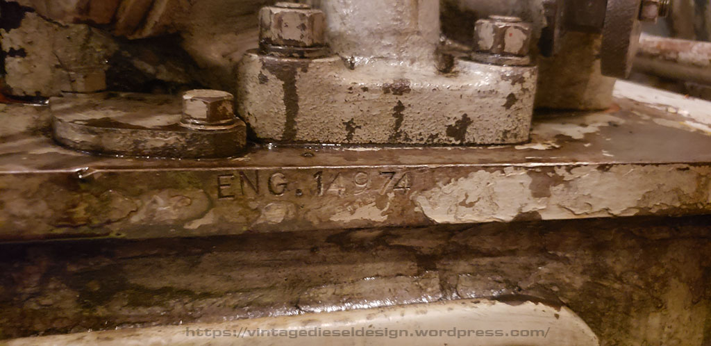
While transiting the Cape Cod Canal, the tug lost oil pressure. Unfortunately, they needed to keep moving, and thus at the end of the day, the engine was destroyed. Ross found an engine out West – Engine 14974, and installed it in the tug as a replacement – The 3rd engine in the “Cornell” (same exact model every time). This is the engine still in the “Cornell” today. Several years ago, my good friend J. Boggess presented me with the Cleveland records above, which is when we found out the engine in the “Cornell”, was actually from the “Cabezon”. There is a 50/50 shot that this is the engine that was almost destroyed while in the “Cabezon” as noted above.
This past July I embarked on a project I have been planning for some time – To repaint the engine finally. “Cornell” was a working boat – And shes a leaker (like all 278’s…EMD learned from this mistake, and put a box around them all!), thus painting was never a huge priority. Since being retired from towing service this year, and with some downtime, I got to it. The project commenced on the Starboard side, with 2 gallons of de-greaser, and lots of rags. I opted to paint her in Aluminum, the original color Cleveland Diesel painted all of their engines. Ill tell you – it was bright. Many years ago, one of the first things I painted on “Cornell” was the fuel lines on the block. Tugs typically have a good portion of the pipelines color coded for easy spotting of what they do – thus yellow for fuel. After repainting the fuel lines yellow, and the over speed trip line brown, I painted the hand hole knobs black, just to help break it up a bit, and give it a bit of her own character.
Original number stamping, found on the forward end of the block. Click for larger.
All done! Click for larger.
Still need to redo the blue on the water lines. Click for larger.
An individual pack. Click for larger.
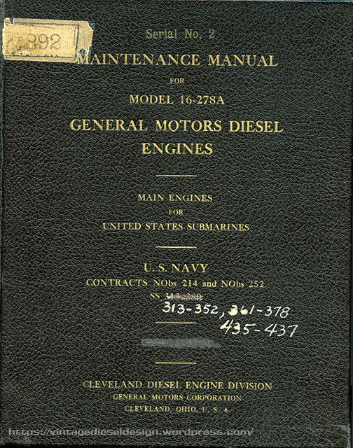
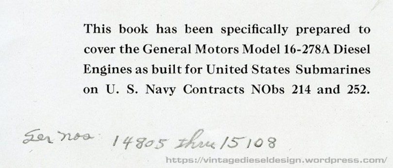
Something on my wish list for several years has been a Cleveland Diesel issued 278A manual, specifically for a submarine. I was able to track one down earlier this year, and best of all, it is specific to the engine in the Cornell.
How the engine appeared out of the factory for the subs. Note it looks like the valve covers are actually polished! When put in the tug, the governor’s were switched over to Marquette’s, as well as the lay shaft arrangement to the more traditional, chest height one. Click for larger.
“Cabezon’s” insignia. At some point, I plan to paint this on the air intake.
“Cornell” spent the better part of the 1970’s for Ross, doing all kinds of odd jobs, including a long trip up to Sturgeon Bay, Wisconsin to pick up the Boston Aquariums new barge. Not long after the engine was swapped, the main generator, quite literally let loose while towing a barge, and was also swapped out. She would go on to work for Boston Fuel Transport/Boston Towing until being sold privately in 2003, and ultimately to Lehigh Maritime Corp. in 2007.
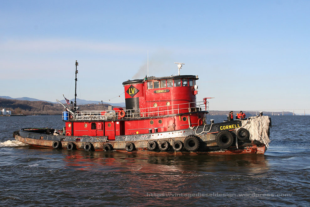
Ill close this post out with a photo of the “Cornell” at work. Now I just need to paint the other side of the engine…and everything else down there…
Ill start with a bit of prequel to this story with some history. The Tug Cornell is powered by a Cleveland Diesel “Navy Propulsion Package”, which consists of a Cleveland 16-278A and an Allis Chalmers 1090kW, 525V DC Generator, mounted on a common base. In turn, this provides power for a Westinghouse 1350HP electric propulsion motor, driving a Farrel-Birmingham single reduction gear. Except for the gear, all this equipment is reconditioned WWII surplus, Destroyer-Escort equipment. Lots more to come on this equipment in a future post.
Both ends of the main generator, as well as the forward end of the propulsion motor are supported by large, oil fed babbit pedestal bearings. The generator ones are fed by the main engine lube oil system, and the propulsion motor one is fed off the reduction gear oil system. The motor only has a single support bearing on the front, as the rear is supported by the reduction gear. In April of 2012, we burned up the aft support bearing on the generator; however, I will save that for later, as I documented this instance better.
Destroyer Escort propulsion motors, were used in pairs on the ship. When resold for commercial service, they were split into single units.
In September of 2015, on a Sunday afternoon, we were just leaving with the tug to head down river, with another small tug (Pilot, Dave’s tug) alongside. The plan was to drop off the Pilot in Verplank, head to the city to pick up a barge, and then back to Kingston as we had training class days later in the week in Kingston. About 45 minutes out, just at the Esopus Meadows light just South of Kingston, I go down and do my engine room checks. I have my routine, I go down the stairs, around the front, back, around, back to the gear, and back up…so, coming around the front, I smell burning. The best way I can describe it is a burning electrical smell. I remembered the smell from when we burnt up the generator bearing. So, I kind of figured it was THAT bearing acting up again, I run around back looking for the thermal gun, and in the process put my hand on top of the motor bearing (part of my routine..), and yeah, at that point I knew what was really happening!
So, I get on the horn to the wheelhouse (we have a radio from
the engine room to the wheelhouse) to go all stop, GET THE PILOT RUNNING!, and
GET DOWN HERE!, I run for the hose to start getting water on the thing. (270
degrees on the shell right now). Dave starts steering, Don runs over and
gets Pilot running (This is after we drained the fuel tanks this week, leaving
only 50 gallons on the day tank…) Matt runs down and helps me start cooling
this thing down with just water and rags. By now, we are just hanging out
in one of the wider parts of the river. Pilot
is running and ready to go alongside and holding us. Me and Don start
tearing the oil lines apart to the bearing. We put air to it, and it shot
a solid slug of crap out…
Now, the forward support bearing, is pressure fed from the reduction gear. Its a very simple system. There is a suction line from the sump of the reduction gear with a check valve, this goes to the pump driven off the main pinion. From the pump, it goes through a cooler, strainer, then T’s off. One line goes up to the support bearing on the motor, and the other goes to the gearbox, for the top spray line, and the pinion and thrust bearings (which are SKF ROLLER BEARINGS!) in the gearbox. All the oil is crystal clear and looks fine. it was just that one slug of shit, in the lowest part of the system. The system is only supposed to run at 110 degrees, at 5-8 psi.
So, we get this thing cleaned out, Pilot is holding us so we don’t
drift all over the place ( Dave’s friend managed to see this from shore!) we
get it back together, but we can’t get the pump on the gearbox to reprime quick
enough to cool the bearing and get some oil to it. We thought we might
have caught it before it went nuclear, but when we turned the excitation on
(When you turn it on, the motor creeps sometimes), we got the nail on
chalkboard sound.
Ok, Time to have Pilot turn us around, and tow us back to the dock. Nothing we are going to do out here now.
Click for larger.
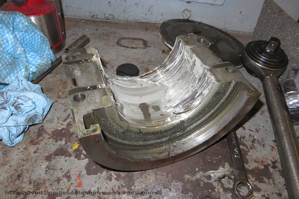
With the upper half of the pedestal removed, and the upper shell removed we saw the damage was done. All of the babbit melted out and then reset when it cooled off. What looks like scoring on the armature shaft, is actually just streaks of babbit.
Upper half of the shell. Click for larger.
Lower half of the shell. Click for larger.
Both halves of the bearing. Click for larger.
Both halves of the bearing shell. Click for larger.
Click for larger.
In removing the lower half of the shell, we made the observation that this has happened once before. Notice on the upper lip where it has been built up with brazing from where the shaft dropped and wore out the shell. Note the two oil drain holes in the center. Also, note the heat distortion. This shell got to over 500 degrees to melt that babbit in that fashion. Luckily, the shell was not warped.
So, a few years ago our fellow engineer friend Tim Ivory built a centrifugal bearing machine, to re-pour the main bearings in the tug “Spooky Boat”s Fairbanks-Morse 35F10M engine. Well, it turned out we were the first to make use of it two years prior when we cooked that generator support bearing. Since then Tim has made several bearings for various projects.
The barge in the city can wait until next week, but the class days Wednesday, Thursday and Friday can’t be rescheduled. Sunday night we got the shell apart. It is only 4 cap bolts, 4 shell bolts, and a pipe fitting into the shell for the oil line. After we got the motor armature shaft supported, the lower shell just spins out.
We were not able to do anything Sunday night. It turned out, Tim already had the bearing machine off the storage rack, and had one of the small, 2″ bearings for Spooky boats 1 Cylinder FM generator mounted in it to re do. We took care of that on Sunday to get it out of the way.
Monday, Matt (Owner of Cornell), had to go to the city and take care of a few things. Great, we found a foundry down there that has the babbitt in stock (Belmont Metals), and we can pick it up. Next, we need gaskets, The bearing mounts to the table using 4 studs and a plate. The shell needs a gasket where it meets the mounting plate, or the hot liquid babbitt just pours out all over. It is a 4″, ring style flange gasket, rated for hi-temp, usually graphite based, 1/8th” thick. We can’t source them locally. I found a place in Brooklyn that has them, I call them, tell them exactly what I need. Ok, fine no problem, 6 in stock. While this is going on, we prep the shell. Simply, melting the old babbitt out.
Melting out the babbit using a roofing torch. Click for larger.
The shell, now cleaned of all old babbit and tinned. Click for larger.
The next issue at hand was that we needed a plug. On the after side of the bearing, the outer edge of the shell rides on the larger portion of the shaft forming a mechanical oil seal. Unlike the bearing on the generator which used a labyrinth cut into the babbit, this bearing just have a tight tolerance fit, and thus we need to keep this entire area clear of any babbit. Tim had the great idea to make a simple one out of the bottom of an old scuba tank!
Making the lower plug from a scuba tank. Click for larger.
Click for larger.
After the bearing is cleaned out and tinned, the halves are bolted together with an aluminum shim plate, which is sealed with hi-temp silicone. The shims create a space so that the shell can be split apart after the babbit is cooled, and the babbit wont stick to the aluminum.
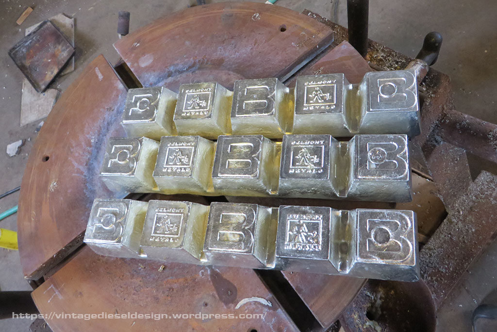
The rear plug is centered up in the rear. Click for larger. New 6lb ingots of babbit from Belmont Metals, in Brooklyn. The babbit consists of 78% Lead, 14% Antimony and 8% Tin. Click for larger.
Now, Matt shows up with the gaskets Monday afternoon…totally wrong thing. Back to the drawing board. I managed to find a plumbing supply house about an hour away. We shoot down, and start telling them what we need, and comes the typical “What is the application..” Our response, “Can you just take us to where you keep them, and we will get what we need?” They take us to them, score! they had what we needed.
Click for larger.
The shell itself is sandwiched into the machine using 4 studs attached to the bed plate, and a steel plate with the center cut out. After a few minutes getting the bearing centered and balanced, it is ready to go. Each of the 4 studs is wrapped in fiberglass insulation to help prevent the stud from stretching, and have stiff springs outside of the plate to take up and stretch while being heated, and even still they are periodically re-tightened. The gasket sits between the top plate and the shell.
Click for larger.
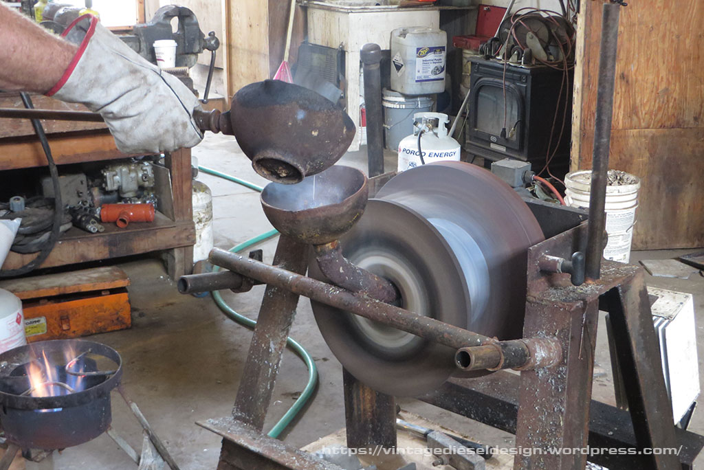
Next up, rotating the assembly down 90 degrees and preheating the bearing using the roofing torch to around 500 degrees. In the background the babbit is being melted.
In goes the babbit. Click for larger. Click for larger.
We melted 12 pounds of babbit and poured in about 9. After pouring, the shell is immediately hit with water to cool it. This is so the shell cools and shrinks from the outside, so the babbit does not crack.
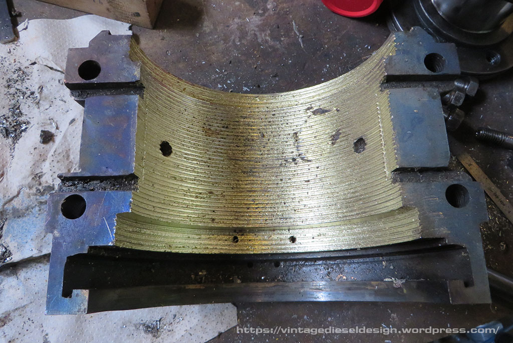
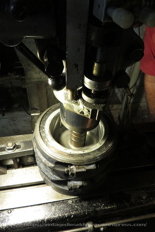
This is how the bearing looks directly after pulling off the outer cover plate. The green is the remnant of the gasket. Click for larger. The bearing after being split apart. It can now be bolted back together without the shims, and be machined. Click for larger. Click for larger.
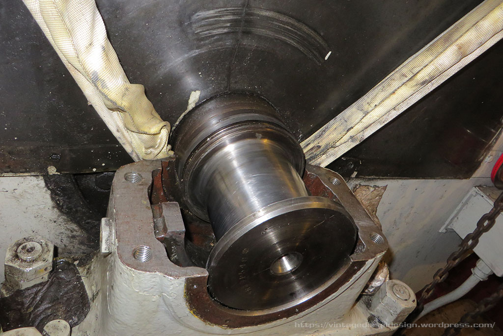
With the new babbit poured, we went back and cleaned up the shaft. It had some very, very light scoring on it that we were able to polish out. We took a slew of measurements, and were now ready to machine it.
Mounted in the lathe and cut to final size. Click for larger.
Cutting the oil wedge’s out on the milling machine. Click for larger.
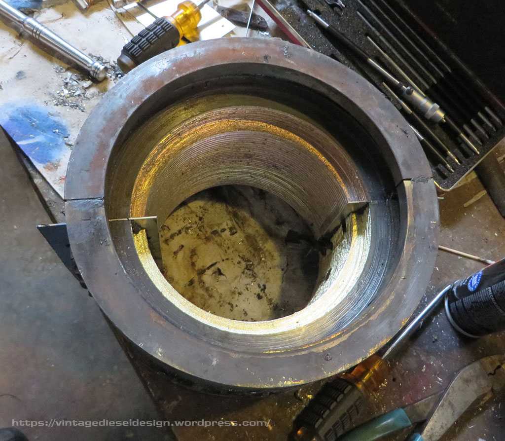
The finished bearing shells. Click for larger.
The propulsion motor, with the shaft supported from the overhead using a chain fall and sling. Click for larger.
Rolling in the lower bearing shell. Click for larger.
We put the thing back together about 11pm on Tuesday, figured out how to get the oil pump reprimed, cleaned all the lines out, and started the boat about 11:15. We spent the next hour running it, getting it scrapped in with a razor blade and bluing dye (run for 25m, take it out, scrape…repeat..). We used timesaver compound (an old timers trick for babbitt bearings, which alot of old manuals for big engines specifically say to use for this exact purpose), to help get it wore in.
The class days we took it easy, no more then 100 shaft rpm (so about 400 on the motor). We never seen more then 100 degrees on it. Here we are almost 4 years later, and the bearing runs perfectly fine, and stays right around that 110 degree mark. For all intensive purposes, we were able to turn this repair around in around 48 hours, completely in house.
Since this happened, not only have we managed to acquire a spare support bearing shell set, but I even managed to find an original Cleveland issue manual, that covered the Generators, Motor and the pedestal bearings for both, with complete spec sheets.
Cleveland Diesel manual covering the Destroyer Escort’s propulsion end.
Blueprint sheet for the forward support pedestal bearings. Click for a larger version.