aka Diesels that look like toasters, Part I.
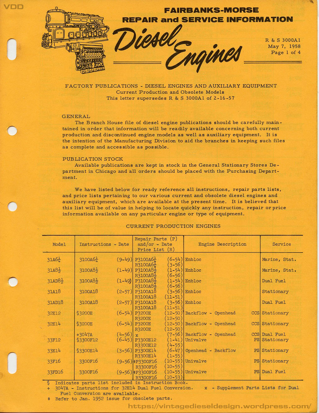
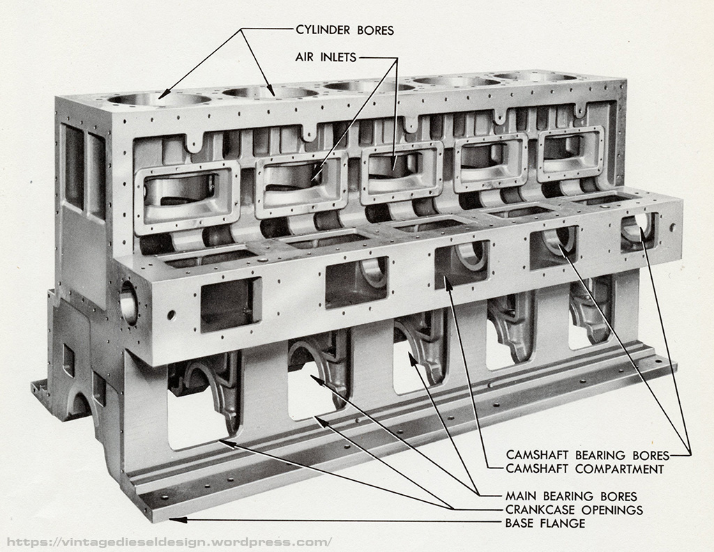
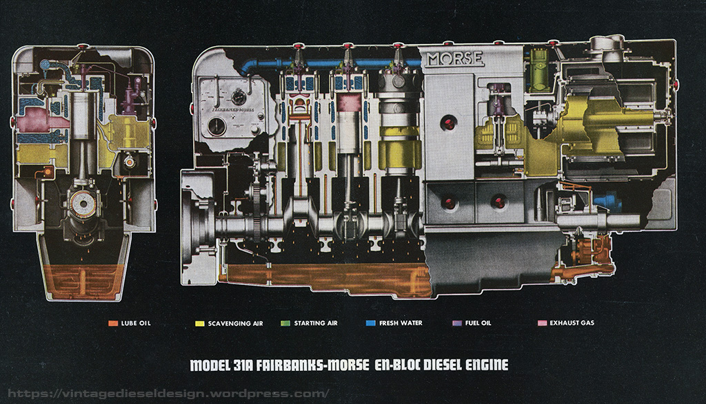
As we outlined in our very first post here, Fairbanks-Morse introduced a line of what they called “En bloc” engines, meaning whole, which to put bluntly, they used a one piece cast crankcase with integrated cam pocket and bearing bores, which F-M advertised as putting all of the pieces in perfect alignment every time. Attached to the block would be the various auxiliary pumps, exhaust belt, water header, blower, etc.
VDD Post on the Fairbanks-Morse 31A18
The F-M 31A En bloc engine seems to have made its first appearances in advertising around 1945. This specific line of 31A appears to be the decedent to the 31A “Borneo” engine. The first real production of this 31A series seem to start around 1949, which is the publication dates of each of my manuals. The 31A was offered in 3 bore sizes: 6 ¼”, 8 ½” and 18”.

The 31A we will be discussing in this post is specifically the two smaller versions of the model, the 31A6 ¼” and the 31A8 ½“. The engines are two stroke, cross flow scavenged, with an integrated scavenging blower, as well as an optional compressor, bilge pump and water pumps. Both models were offered in a direct reversing marine model, or a stationary model, and in the case of the larger 31A8 ½“, a dual fuel version. An additional option on the direct reversing marine engine, was a reduction gear with an Airflex clutch (note- this is not a reverse reduction gear, the engine is still direct drive). Both models were available in either rotation.
31A6 ¼”: 6 ¼” bore, 9” stroke
Marine & Stationary Engines – 720RPM
5 Cylinder – 150HP
6 Cylinder – 180HP
7 Cylinder – 210HP
8 Cylinder – 240HP
31A8 ½“: 8 ½” bore, 11 ½” stroke
Marine Engines – 540RPM
5 Cylinder – 312HP
6 Cylinder – 375HP
7 Cylinder – 437HP
8 Cylinder – 500HP
Stationary Engines – 514RPM
5 Cylinder – 325HP
6 Cylinder – 390HP
7 Cylinder – 455HP
8 Cylinder – 520HP
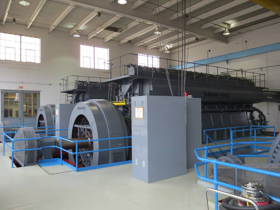
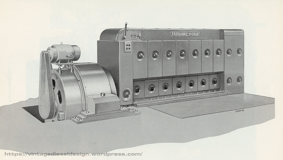
The cool part about the 31A engine line – it was a fully enclosed engine. Removable covers covered the entirety of the engine, front to back, with a very 1930’s Art Deco type look to it. It also looks like a toaster, and this will be the first model we cover in a series of “Engines that look like toasters”.

While the engine is offered in two sizes, they are virtually identical engines, much like how the F-M 38 series (5 ¼” and 8 1/8” bore) were designed – parts were just “scaled down”. The notable difference being that the smaller 31A6 ¼” used a timing chain for the camshaft drive, while the 31A8 ½“used a gear drive. It seems to be that the larger 31A8 ½“ was much more common then the smaller bore, which seemed to be popular in smaller work boats.
Let’s do a quick walk through of some of the features of the 31A.
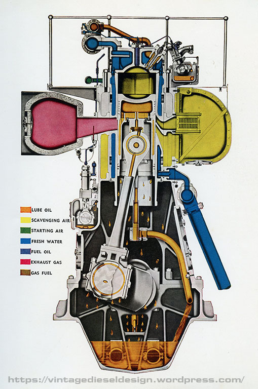
Up on top, the 31A used a very basic lump of a cylinder head, like most of the previous F-M engines. A central fuel injection nozzle, along with a start air check valve, and a space for either a test cock or a start cartridge adaptor. The cylinder heads bolt down onto the liners, with a simple copper gasket between the firing surfaces, and rubber rings on the water passages.

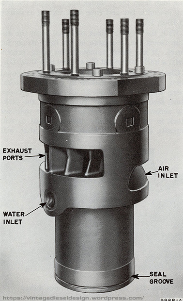
Unlike most previous large F-M engines which the cylinder liner sits on top of the main crankcase, the 31A uses a cylinder liner that inserts into the block. The air inlet ports, and the exhaust ports are surrounded by a water jacket supplied through an unorthodox method. Cooling water enters the engine into the (water jacketed) exhaust manifold. A threaded fitting allows water to exit from the exhaust jacket, into the lower portion of the liner, flowing up through the head into a water header. On the bottom of the liner was a simple O ring to seal the scavenging air from the crankcase.
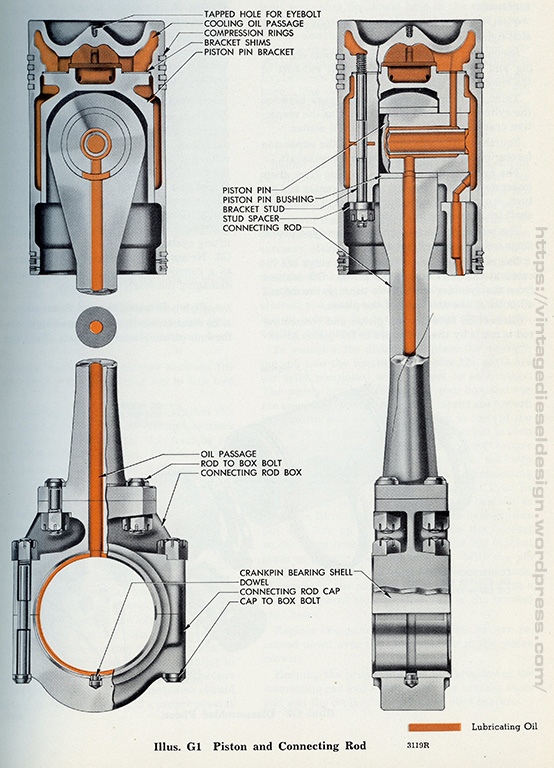
The 31A series engines use only a conventional style full pressure oil system (unlike other models which used a combination of force feed Madison-Kipp lubricators as well as a pressure system), which force feed all of the bearing surfaces, as well as drilled crankshaft which feeds oil to the connecting rods and pistons. The bearing shells for both the upper and lower main bearings, as well as the crankpin bearing shells were all interchangeable.
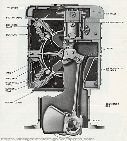
Scavenging air for the 31A series is provided by an attached vane style, oscillating blower. In layman’s terms, it’s a big moving flap. Incoming air comes in through a set of intake valves, gets compressed (1.5-3psi), and exits into the airbox through a set of discharge valves. The moving vane is run off its own connecting rod on the forward end of the engine. Intake air could be routed through the top, or front of the engine. Engines so equipped with a compressor; this was driven off the lever that runs the blower vane.
Under the hood on the control end, things are a little more complicated. To maintain the streamlined appearance, all the control rods are inside. Follow the diagram – Incoming fuel comes into the fuel header on top of the injection pumps. Each injection pump is driven off the camshaft. The fuel rack on the pumps is controlled by the governor – in this case, a direct reversing marine engine, using a Woodward SG8 governor. Governor speed is controlled by a speed lever. The governor is driven off the camshaft, which also drives the fuel pump, as well as a very basic, mechanical overspeed governor trip system. Engine direction is controlled by a separate lever, which controls an interlock on the air side (to prevent the engine from starting if it is still moving in the opposite direction).

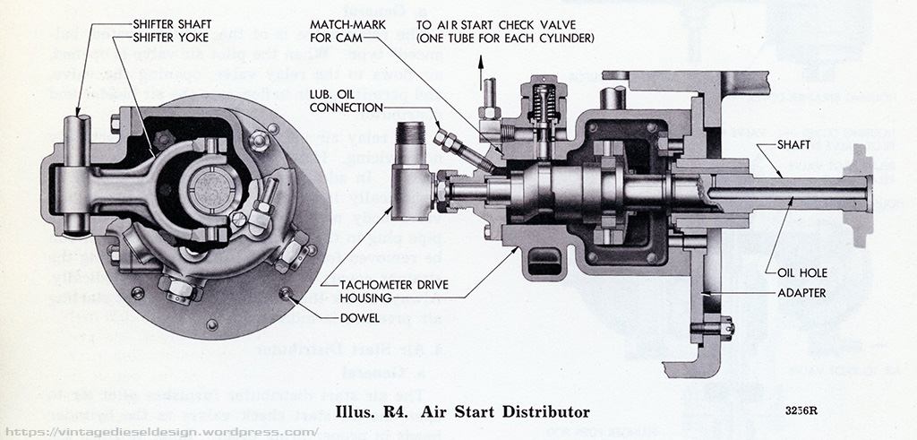
Moving on to the air system: The shift lever controls a rather complex pilot air system. Driven off the camshaft gear drive train, is an air distributor. Think of this like a distributer in a car. Instead of controlling the firing order of spark plugs, it controls the air start sequence timing. Putting the lever to start, air from the pilot valve, opens the air start relay valve, thus filling air header with start air. At the same time, air from the distributor. opens a check valve on the appropriate cylinder, thus letting the start air in. The same lever also has a cam that is tied into the fuel rack and governor, to set the fuel load when either in the start or run position. In order to switch from ahead to astern, the shifter lever also controls a shifter cam, which in turn runs down to a shift fork inside the air start distributor. This shifter moves a small camshaft to choose the appropriate timing for ahead or astern starting.

Stationary engines still use the same system; however, it is slightly simpler without having the additional moving shifter and gear for the reversable timing. Stationary engines used a Woodward UG8 governor, with a faceplate and knobs for the extra controls.
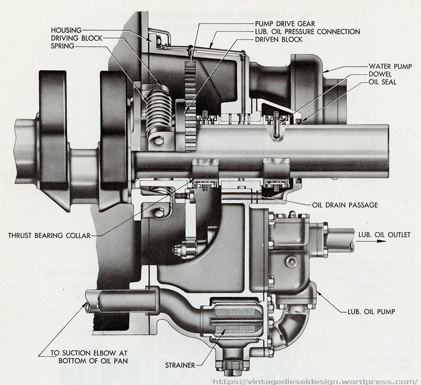
Unlike the larger 31A18 engine, these smaller engines have more provisions for attached pumps. All the pumps (oil, raw water, soft water) are driven off the crankshaft through a flexible drive gear (a spring pack drives the gear to absorb any shocks) located under the blower. In the case of the direct reversing engines, all the pumps are reversable (except the fuel pump, which has a directional switching valve). One of the options for marine engines was a small reciprocating bilge pump that was driven off an eccentric on the cam idler gear. Behind the flexible drive gear was the thrust bearing. Often in cases of stationary engines, water pumps were typically electric driven pumps.
Both models of the 31A included an unusual option – either an Airflex style clutch and a reduction gear, or a Twin Disk clutch. This clutch was simply an “on – off” per say. The reduction gear would be built to match a vessel’s specific. The Airflex clutch was also available for stationary applications and could be offered on either end of the engine.

In the case of the 31A8 ½“ engine, an optional dual fuel version was offered, the 31AD8 ½“. While the specifications are the same, the AD engine included a few additional parts in order to run on both Diesel and Natural Gas – however, Diesel was still used as a pilot fuel. On the control side of the AD engine, tied into the control lever is a pilot valve, which controls an oil pressure activated gas shut off valve – which is also tied into the governor overspeed – thus, if the engine overspeed’s, or shuts down for any reason, the natural gas is shut off. On top of the engine, a gas manifold runs alongside the cylinder heads. On each of the cylinder heads is a valve, which is operated by a set of push rods and rockers off the main cam shaft. The fuel injection pumps are a duplex style, that when the engine is run in Diesel mode, the normal amount of fuel is injected, however when operating in dual fuel mode, a smaller metered amount of Diesel is injected as a pilot fuel for the Natural Gas. When running in Diesel mode, the gas injection valves are still functioning, however nothing happens as they open when the exhaust stroke starts.

Fairbanks-Morse 31A Gallery


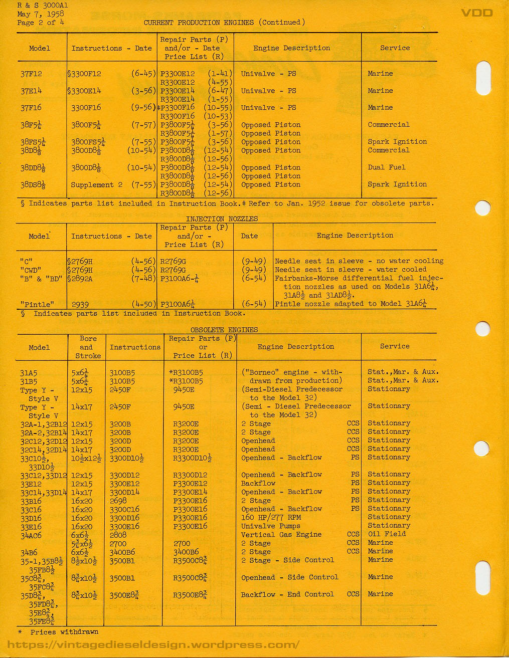
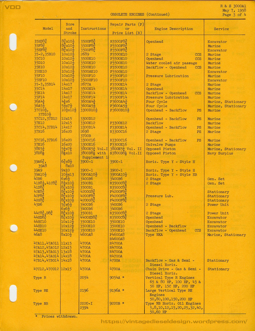
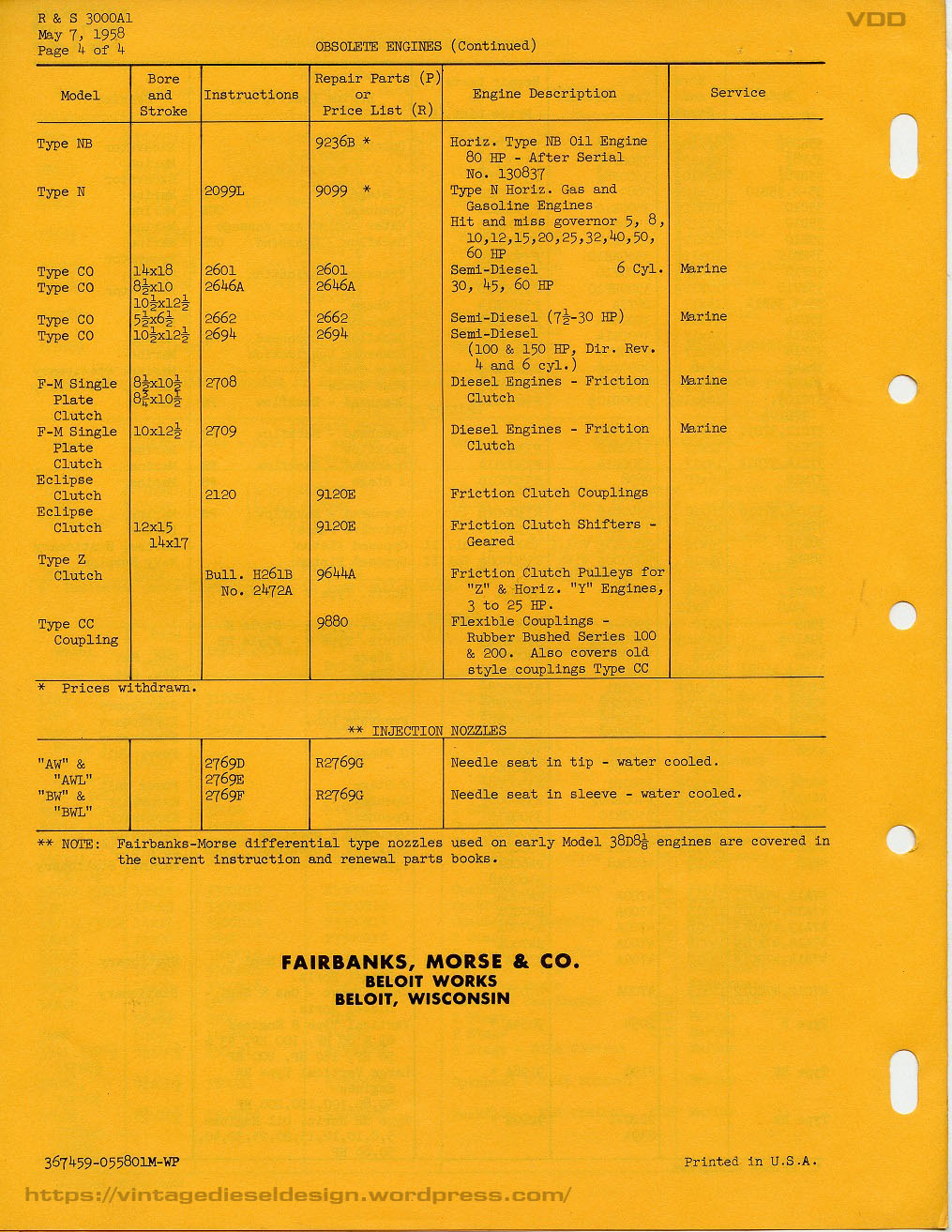
The F-M 31A series (with the exception being the 18” bore for stationary power generation) never really caught on. By the 1950’s when F-M was really pushing the engines, there was already smaller and lighter engines making around the same power. Not to mention, the plethora of cheap WWII surplus engines, including many F-M 38D OP’s which went on to do just about every job under the sun. By 1958, F-M severely reduced engine production to just the 38D OP engines (in both bore sizes), the 31A18, and the small 45C and 49B engines. All of the older models were now discontinued (such as the 31A, 32D, 37F, 33D: any of the older pump or crankcase scavenged engines). One of (the?) last running example of a 31A8 ½” was the NOAA research vessel “John N. Cobb”, which was operational until 2008 when the crank snapped. The vessel has recently been sold for use as a fishing boat, and I would imagine will be repowered. The small, former Canadian buoy tender “Nokomis” has a 31A6 ¼” and has been up for grabs for some time now, if it has not been scrapped yet. I imagine there may still be a handful of older stationary examples hiding around the country somewhere. W.W. Williams became the parts supply company for these engines when F-M gave up the rights, however nothing has been available for quite some time. Interestingly enough, Williams listed a 4 3/8” as well as a 10 ½” bore 31Aengine, however I have seen nothing about this in any of my F-M company literature, production lists or any advertising of the period.

As always, I welcome any questions, comments, corrections, etc.. I would love to hear if any more of these engines are out in hiding. I have manuals for all 3 sizes, as well as the parts book for the 18″ should anyone need a copy. Since I know I will likely never get to play with any of these big old engines, I started the CAD work to 3D print a scale model..the first of many engines I plan on building.