
I will begin this by saying I am not writing this post as a history and operation of the WWII LST, or Landing Ship, Tank. There is plenty about that on the web, thus I defect. I will include some links in the last part of this series for some further reading. For this, I want to cover the propulsion side of things. This will be another 4-part series, and be warned, these posts will be photo heavy!
August 1941. The US and British join their naval forces to pool ideas for a new era in landing ships. The British already had a design they were building, however the US opted to go a different route seeing the success, and failures of the previous classes of ship. Working with Gibbs & Cox, John Niedermair of the Bureau of Ships refined the basic British design into what became the LST (2) class of ships.
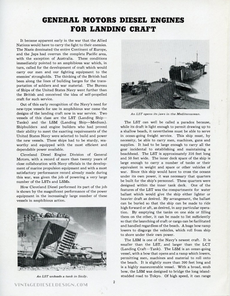
The “S” in LST told us of the scale. These were ships! Abit, a smaller one. The LST would come in at 328’ long, with a 50’ 11 ½” beam. Originally contracted as the Atlantic Tank Landing Craft (or ATLC), the ship had to be able to safely cross the Atlantic Ocean from stateside, and reach the beaches of Italy, Normandy, Africa, and others. LST’s were designed with a shallow depth in mind – only 8’ on the bow with a full load, thus the LST could do what it was designed for: Land on the beaches.
A pair of LST’s are loading in France, 9/4/1944. Click for larger. National Archives
The purpose of the landing craft was to do just that – land on the beaches and deliver a load of tanks (and everything and anything else!). The tank deck itself was 203’ long, and able to carry 18 Sherman tanks and 160 troops. On the upper deck (reached via an elevator) would be room for smaller wheeled vehicles, and/or 4 LCVP (Landing Craft , Vehicle, Personnel or Higgins boat) hung on davits.
The original British design of the LST had a downfall. They were steam-powered with reciprocating and later steam turbine engines. Now, in the era, steam was of course still reigning king. However, when the orders came down for the LST, it just made sense to go the Diesel route.


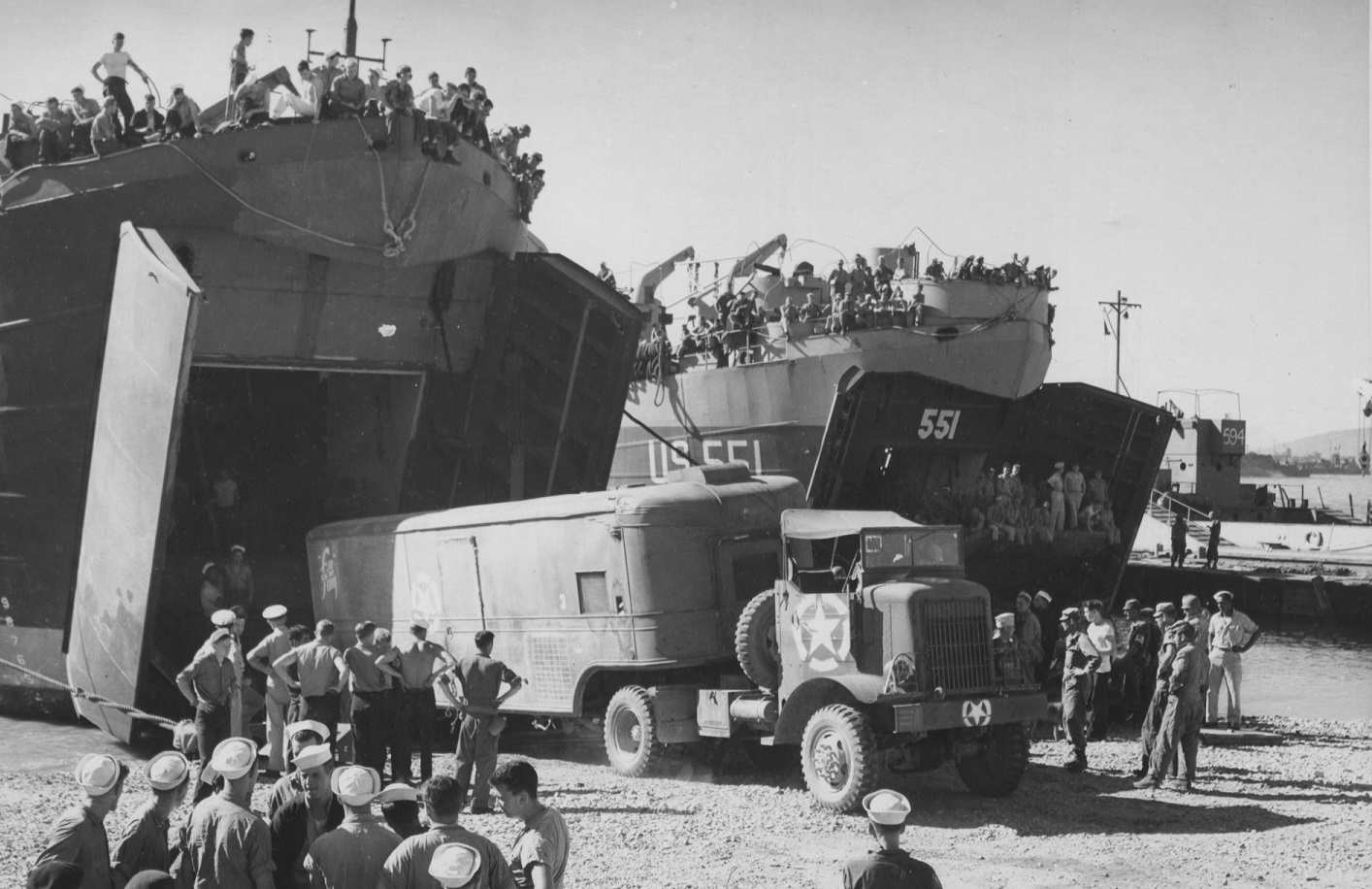
Left: A trio of LST’s are on the beach in Manilla, in the Philippines. The city was liberated from the Japanese in March of 1945. Click for larger. National Archives
Right: Equipment being loaded for the 12th Detachment of the 20th Army Airways Communications aboard LST’s in the Solomon Islands on 3/24/1944. Click for larger. National Archives
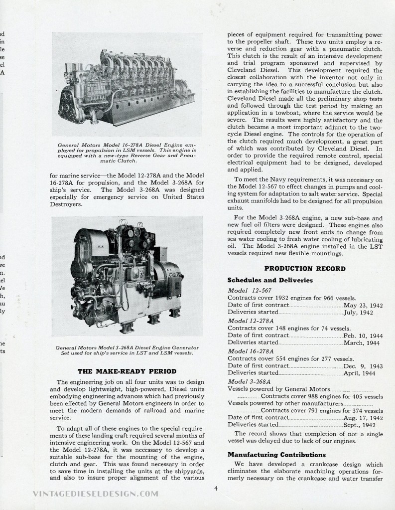
By the time the US had entered the war in December 1941, Electro-Motive Corporation’s 567 engine had proven itself. The engine was successfully raking up miles in the FT locomotive (soon to be put on hold for war production of the LST engine in 1942 but would resume briefly in 1943 for the AT&SF and others), NW switchers, E units and other locos. On the marine side, the engine was already used successfully in some US Navy fleet tugs, USCG cutters and a handful of tugboats. The engine selected for use in the LST was the 12-cylinder version, like that in the NW2 switcher. At the time of the LST orders, the 567A model was newly introduced into production. The engine designation used for the LST would be the 567ATL: which stood for the original designation of Atlantic Tank Landing, with either an S or a P added to the end for its rotation, Port or Starboard, since the twin screw boat would require counter rotating props. We will explore some of the features that set this engine apart from previous 567 models further down this post.
“To demonstrate to the Navy what our engine could do a 12-567 was taken from locomotive production and put on a test stand and run for fifteen days. It produced 960 HP at 720 RPM; and then, without stopping the test run, the load and speed were stepped up and the engine run two more days, producing 1200 HP at 800 RPM.” – EMD in Diesel War Power
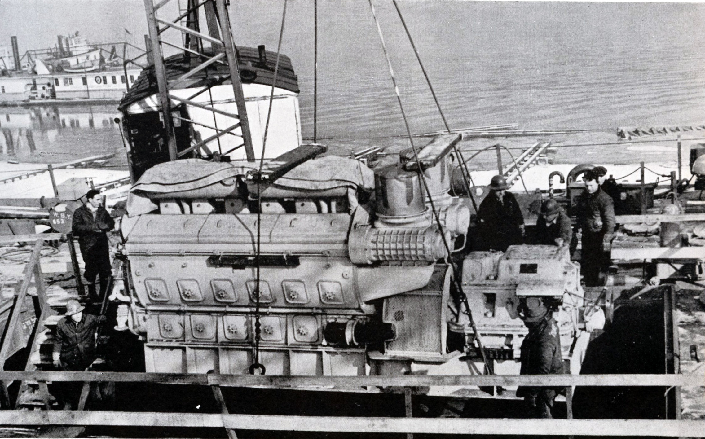


Left: A new engine being lowered into an LST at Dravo’s Neville Island (Pittsburgh, PA). Dravo would build 185 LST’s between December of 1942 and May of 1945, along with a slew of Destroyer Escorts, LSM’s, Lighters and many other Navy craft. Click for larger. EMD Photo from Diesel War Power.
Center/Right: A new 12-567ATLP illustrated for the Maintenance Manual. Click for larger. Cleveland Diesel Photos.
Now – It is worth noting, as has been said on this blog many times before, that all Marine 567 engines were ordered and sold though Cleveland Diesel. The case of the 567ATL is a bit muddled in history. Until I can find the time one day to explore the Bureau of Ships orders at the National Archives, it will remain muddled. What we do know – Cleveland Diesel was the prime contractor for the LST program. I have been told the engines were indeed ordered through Cleveland Diesel – however they could not do the required conversion and fabrication work as they were already knee deep in 278A orders for submarines (and literally everything else that floated…), thus EMD would do all of manufacturing work in-house. EMD covered this in their “Diesel War Power” book, but what we do know is Cleveland Diesel did the R&D work, supplied all the manuals, drawings, parts, as well as promotional material. But at the end of the day, this was indeed an EMD product.
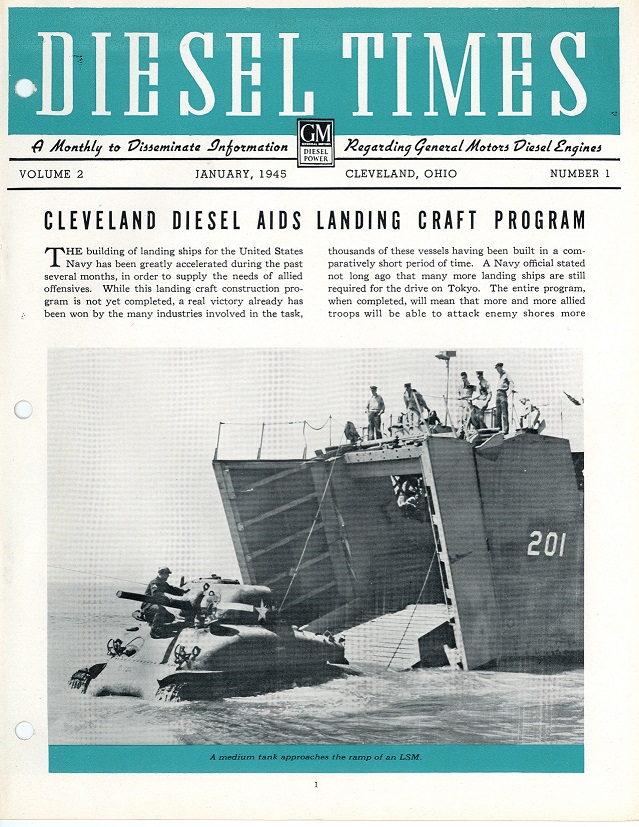
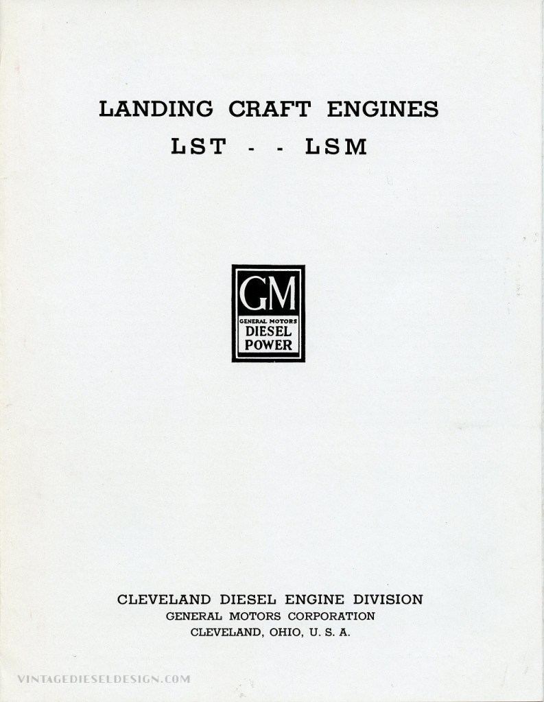

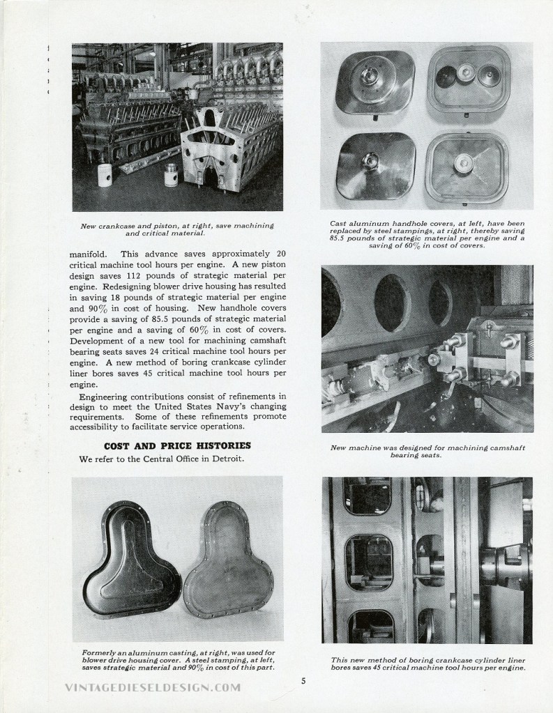

A 6 page booklet put out by Cleveland Diesel which describes the LST and LSM program, as well as the engines that were supplied to them. Production totals noted here are slightly off from the actual records. Vintage Diesel Design Collection.
While the intent of this is to talk about the 12-567ATL engine, it is also worth briefly mentioning some other landing ship and landing craft engines supplied by General Motors. Along with 567, EMD also developed (in conjunction with Detroit Diesel) , the Quad 71 engines used in Landing Craft, Infantry (LCI). This took 4 off-the-shelf Detroit Diesel 6-71 engines and assembled them into a common base with an EMD-designed reduction gear, propeller shaft, variable pitch propeller and control system. Two of these quads (900HP each) were installed in an LCI. With the variable pitch control, the landing ship would be able to run onto the beach at power and make a quick reverse move without the need for the engines to slow down. The Detroit 6-71 (the Detroit/Grey Marine 6-71/64HN9 will be a future posting) itself would be used in the Landing Craft Vehicle Personal (LCVP). Over 20,000 of these small plywood boats would be built during the war and were one of the ships credited to helping with victory. 6-71s also graced the LCT (Landing Craft, Tank) and Landing Craft, Mechanized (LCM). The final GM engine – the Cleveland 16-278A was utilized in the Landing Ship, Medium (LSM). The LSM was slightly smaller than the LST at 208’, allowing them to be a little quicker, with more horsepower than an LST. Fairbanks-Morse would also supply propulsion for LSM’s using direct reversing 38D 8 1/8 OP engines. Another engine worth noting is the 8-567ATS (noted as 8-567AM in the records). These 700HP engines were contracted in 1943, and used the same basic marine modifications used by the ATL engine, they were simply a smaller size, with smaller gearbox. The engines supplied propulsion for a class of 100 identical tugboats, built for the Defense Plant Corp., or DPC. Cleveland Diesel did supply 148 off the shelf 12-278A’s for the LST program as well, mated to the Falk gearbox.


Tables from “Propulsion Diesel Engines for Landing Craft and Small Boats”, written by Capt. H. Ambrose, Cmdr. G.C. Humphreys and Lt. Cmdr. F. E. Swiderski. Table on the right has been noted with which engines were used on each type of boat. Note that they mention the Fairbanks in the LSM as an “38RD 8 1/8”, signifying it as being direct reversing, however FM did not use such a model designation. Click for larger.

Left: Early into the Korean War, LST 611, 745 and 715 are on the beach at Inchon, Korea on 9/15/1950. Click for larger. National Archives
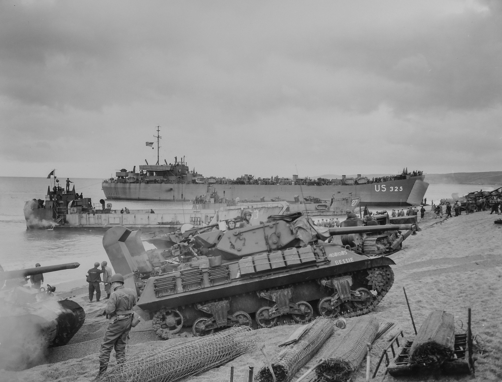
Center: LCT 153 in the foreground, and LST 325 are on the beach in England, loading in preparation of the Normandy Landings. Click for larger. National Archives
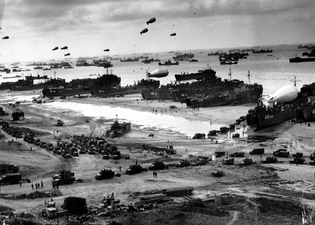
Right: One can see just the scale of the Normandy invasion in this photo, with 15 LST’s on the beach at Omaha. Troops and supplies are unloading for the push into France. Click for larger. National Archives
Back to the engine we started to write about! The 12-567ATL. As we mentioned above, the 567 engine was already a success, however it did have a few downfalls for use in maritime use. The original engines (567U) used several iron castings; the top deck, cam pockets, etc. The navy wanted engine shock resistance (Important for when you’re being shelled at or hit by even near misses by the Axis!), so those castings had to go. One specifically was on the top deck of the engine where the exhaust exits the block. EMC revised this with a weldment (the 567V), but it was still a large open area on the top, with numerous gaskets as well as a deep valley for oil and water to collect in. Another simple issue was the engine was too wide. The blower drives hung way outside the width of the basic engine. The engine also needed a separate water pump for raw water cooling. When the USCG ordered their engines in 1939, they custom-ordered their engines with a narrower drive.


Installation drawing for the 12-567ATLP. The ATLS engine was a mirror image to this. Click for larger.
The “new” 567A engine would address all these concerns. The entire top deck of the engine was redesigned where the exhaust leaves the engine. It is now not only all-fabricated and raised up, but also is now water-cooled. Taking upon the USCG order, the blowers were now permanently moved inboard. The engines were now 5’ 4 7/8” wide overall, versus the 6’ ½” of the older engine. The first engine built for the ATL order was tested in July 1942, with the first production LST accepted in October 1942.
EMD would begin ramping up production for their war work as early as 1940, when they began production of the 184A, 16-cylinder radial engine used in sub chasers. By early 1942, EMD was already working on plant expansion to handle the massive LST engine program, on top of the other war work mentioned elsewhere.

The 12-567ATL was rated for a mere 900HP, at 744RPM. The engine has an 8 ½” bore, and 10” stroke. It would be mounted with its reverse reduction gear on a common fabricated base, thus allowing the shipyard to install this all as one unit, thus saving the time of having to line everything up in the ship itself.
Piston development was an early issue that EMD faced, that went through several revisions. The 567 up until now used a traditional one-piece cast piston with basic wrist pin setup – connecting the piston itself to the connecting rod (be it fork or blade side). Midway through the LST engine production (late 1943/early 1944), a new two piece piston was developed based loosely upon designs used in the 184A radial engine. In the new design on the 567, the piston portion sat upon a thrust washer on a separate piston carrier. The piston itself was able to rotate in the liner on top of the carrier. Holding the piston to the carrier itself was a large snap ring, which was only in place to hold the piston to the carrier during engine startup, as the compression and power strokes of the running engine would take care of this in operation. This new design proved to work out extremely well, and as per E.W. Kettering in his 567-development paper, was pushed into service when the foundry making the previous design could not keep up with the war production.

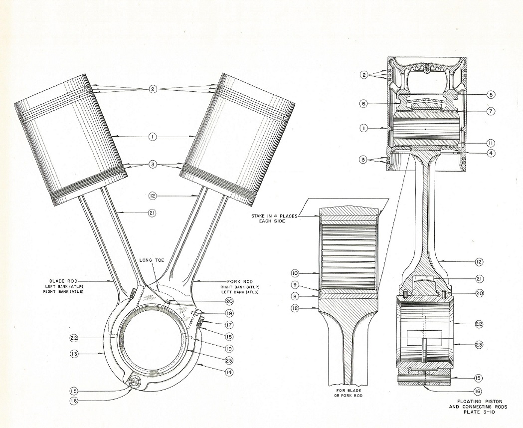
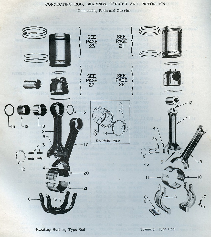
Left: The original 567’s, and into the 567ATL utilized a traditional single piece cast piston, essentially a holdover from the 201A (which used Aluminum pistons), in which the piston was held onto the connecting rod with a wrist pin. EMD uses a fork and blade connecting rod that share a bearing on the crankshaft. Click for larger.
Center: Production moved into the floating style piston, in which the piston rides on top of a piston carrier, sitting on top of a thrust washer. The wrist pin itself is also floating in a bushing. The actual wrist pin itself has gone through numerous design evolutions on its own, like most parts of this engine. Click for larger.
Right: There are two styles of the floating carrier based piston, the left style which uses a floating wrist pin bushing. On the right, is the newer bolted trunnion style, which was another idea based on the 184A pancake engine. This style of piston was introduced late in 567B production, and became the new standard, and was something offered on later upgraded 567ATL engines, which we will talk about in part 3. Click for larger.
Speaking of manuals, There are several! As mentioned above, I have never seen an EMD issued manual for these engines, they are all issued under Cleveland Diesel. What I do have though, is an EMD issued parts book from 1943. There are still more versions of this manual that will we see in the next part.


Left: March 1943 Issue covering the initial order of LST’s under NObs Contract #194. Click for larger.
Left Center: April 1943, covering the 12-567ATL engines diverted for Patrol Craft. Click for larger.
Right Center: January 1944, updated with the new floating piston. Click for larger.
Right: August 1943, EMD issued parts book. Click for larger.

Patrol Craft 882 off the coast of California in 1942. Naval History & Heritage Command Photo.
Note that the above 1943 manual covers order Nobs 217, for Patrol Craft. The PC was a small “in between” ship for escort duty and sub chasing in convoys. A small block of about 100 (we need to go count them..) 12-567ATL engines were diverted out of the LST program and utilized for these Patrol Craft. While the manual covers states they are for PC 827-920, not all of these received the 567. Some would get 12-278As, and some would get Cooper-Bessemer’s. A number of these small ships were built for the Lend-Lease program. Unfortunately, like the LST, these were a bit underpowered, and not noted for speed. We will include some more links about the Patrol Craft in our Part 4 bibliography.
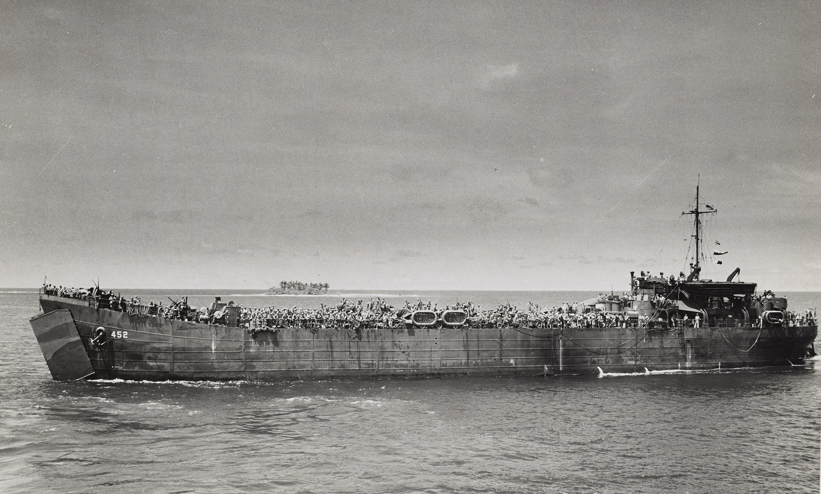
Left: This photo shows us exactly why these ships were called Large, Slow Targets. They were exactly that. LST 452, crewed by the US Coast Guard, has her bow doors open and is about to land on Cape Gloucester, New Britian in December 1943. Click for larger. National Archives
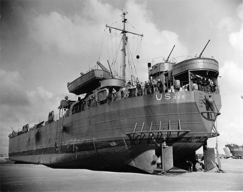
Right: LST 325 (which we will be exploring more of shortly) shows off some distinctive LST traits in this photo while sitting on Omaha Beach. Her long, flat bottom allowed the ship to not only land on the beach but could even sit there after the tide dropped out under it, with no worry about damage. Hanging off of the stern is an anchor, which in most cases would be dropped on the way in, to help winch the ship back to sea at the end of the operation. These constant tension winches were designed by Almon Johnson and would be the basis for a line of very popular tugboat winches, still made today. Click for larger. National Archives
Pushing the LST through the water was another item that was relatively new on the scene: A combination reverse-reduction gearbox, with air clutches. The gear drive was introduced a few years prior in 1939, in the towboat Bull Calf. A 12-567 (one of the earliest used) was chosen to power the small towboat, with the Falk-built gearbox. Inflatable air clutches attached to the flywheel would inflate or deflate, thus forcing the engine to drive either the ahead or astern pinion in the gearbox. This drive style would really take off after the war as a tugboat drive, due to it being much cheaper and more compact than Diesel Electric.


Left: What was only an experiment in 1939 as a combined effort between Falk, EMC and Cleveland Diesel, the combination of air clutches and a combined reverse and reduction gear would be perfect for the LST’s coming into play very shortly. This 12-567 was shipped 4/28/1939 and made a mere 750HP at 660RPM. Click for larger. EMD Photo from Diesel War Power.
Right: The Bull Calf was a very simple towboat owned by the Canal Barge Inc. Company, built by Nashville Bridge Co. She was one of the early Diesel powered craft, in a world still ruled by steam powered sternwheelers. Canal Barge resurrected the name in 1995 on a modern towboat as a nod to history, which is still in operation today. Click for larger. EMD Photo from Diesel War Power.
LST production would encompass 1,052 ships, built by 15 different shipyards. 2,140 12-567ATL engines were built for both the LST and PCE programs. An additional 148 12-278A engines were built for the 74 LST’s that received those in place of the 567. Post war LST’s would receive 16-278A’s.
How about we take a walk through an LST engine room now? We are lucky to have a pair of original LST’s as museum ships in the country. LST 325, based in Evansville, Indiana, is still fully operation and tours various ports on the Ohio and Mississippi Rivers. LST 393 in Muskegon, Michigan, is a moored museum ship. Both of these are amazing vessels and were both on the beach during the Normandy Invasion. Right now, we are just going to take a look at the engine spaces. In Part 4 we will explore the ships as a whole a bit more and show you all around an LST.

Thanks to the San Francisco Maritime National Park Association, we can take a look at the booklet of general plans of the LST-983. The above cropping gives us an overview of the engine room on the LST. Towards the left center, we have both main engines. In-between them are the heat exchangers. Behind that are some various pumps. On the right, is the auxiliary generator room, which is separated by a bulkhead.
LST 393 is a fully restored museum ship. The ship is open for self guided tours, where you get to see the full ship. To access the engine room, one needs to climb down a ladder (see drawing, smack in the center on the top). Navy boats were not exactly the most easily accessible.
One thing we have not talked about much is the auxiliary power for the LST, which all had three engines. Two main engine types were used, Cleveland Diesel 3-268A’s, and Superior GDB-8 engines. Unfortunately I do not have the breakdown as to what engines went where, but it appears the Superior engine was much more wide spread.

The Superior GDB-8 is an 8 cylinder, 1200RPM engine that makes 152HP. The engine has a 5 1/2″ bore and 7″ stroke. A 100kW shunt wound generator was supplied with it. The Cleveland 3-268A, which we have talked about plenty on this website, was rated for 150HP at 1200RPM, also paired with a 100kW generator. Click for larger.


Unfortunately, these LST engine rooms are tight! I took these photos several years ago before really getting into researching these things, so they are not the best. This is the starboard side engine, or ATLS, meaning it is a counterclockwise rotating engine. The engine room is fully restored and immaculate, although the color of the engines themselves are..interesting. Click for larger.


Left: As built, the LST’s were operated as bell boats, using an engine order telegraph system in the front of the engine room. In front and to the sides are the various gauge displays. LST 393 has a small bit of modern alarms from her days as a ferry boat in the 1960’s-70’s. Click for larger.
Center: Looking aft into the starboard side shaft alley. Click for larger.
Right: The Port side ATLP engine. Click for larger.


This photo from the rear highlights another interesting thing about the engines. Note that the left hand, port side ATLP engine has a gearbox built by Lufkin, whereas the right hand, starboard side ATLS engine has one made by Falk. This was another case of war time production. Falk alone could not handle supplying these clutch and gear units alone, so they licensed production out to Lufkin Foundry & Machine Co., Emsco Derrick & Equipment Co. and Parkersburg Rig & Wheel Co., on top of building them in house at Falk whom also had Link Belt and Watson-Flag subcontracting for parts being supplied. The reduction gear had an ahead ratio of 2.48:1 and an astern ratio of 2.52:1. Click for larger.

Something rather interesting about these engines was EMD’s use of a single large, brass builders’ plate on them. One would think with war time shortages, the brass would be used elsewhere. These are the only EMD engines I have ever seen that had brass plates, EMD typically using stainless steel. The plates also had all of the contract info, basic engine specs, shipping date and serial number.
LST 325, while it is still a museum ship, is a fully operational museum ship. She is based in Evansville, Indiana (once home of Missouri Valley Bridge & Iron Works – builders of 171 LST’s, although 325 is not one of those). The 325 is open for tours, however being fully operational still – the engine room is not part of the general tour route. The 325 does yearly trips around the Ohio and Mississippi rivers. Again, we will do some more in depth exploring of the LST 325 in Part 4 – right now we will focus on the engine room. My co-author Jay Boggess was able to arrange an engine room tour, thus all of the following photos are his.


Left: 325 has had her original generators replaced with a trio of “modern” Detroit 6-71’s, likely something done while she was in service in Greece. Click for larger.
Right: A portion of the ships service switch board. Click for larger.
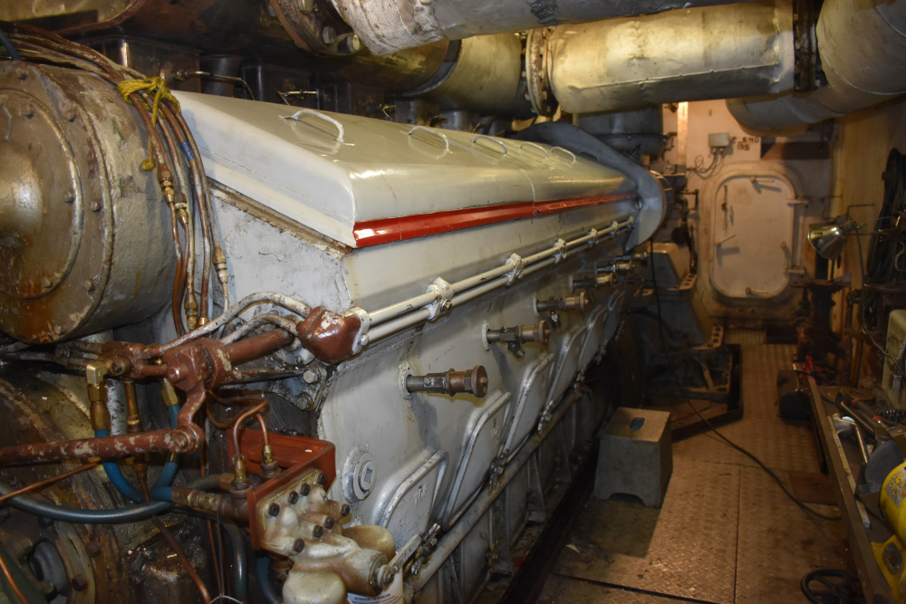
Left: The Port side ATLP on the 325. Note how they color coded the top deck covers red, to associate with the port side running light color. Click for larger.
Right: One of the modifications needed to make the 567 more of a marine engine, was to convert the large exhaust manifold on top to water jacketed. A locomotive style dry manifold would throw an exorbitant amount of extra heat into the engine room. Click for larger.

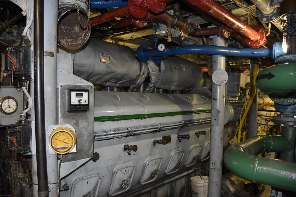
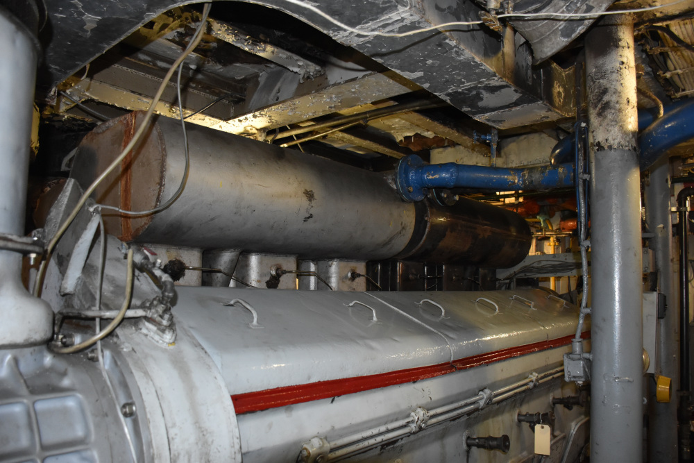
Left: Now we are on the other side, looking at the (green) ATLS engine. Click for larger
Right: Note that this side has a thermal blanket over the exhaust, for that much more insulation. Above the pyrometer is an air vent. Click for larger.


Left: In between the engines are the jacket water and lube oil heat exchangers. Click for larger.
Right: The back of the engine room has some various transfer pumps, starter boxes and reduction gear head exchangers. The access to the engine room on 325 has been modified with a much easier to use staircase. Click for larger.


Left: The front view of the ATLS engine. These used Marquette governors (which were rather uncommon on EMD engines). One of the modifications done to make these usable in marine service is converting one of the water pumps to be used for the raw water (left, or green) side of the cooling, with the other pump still being used for the jacket water (right, or blue), but with a small jumper pipe that crosses over to the other bank of cylinders. On the floor directly in front is the raw water strainer to keep the marine life and trash from going on a trip through the pump and heat exchanger. In yellow are the engines’ oil pumps. Mounted on the overspeed cover is the fuel pump. Click for larger.
Right: The engine space is rather tight down here, with pipelines, pumps and electrical lines running all over the place. Most of this stuff on a tug is under the floor plates. This is a good view of the reduction gear, which splits into several pieces for maintenance. Click for larger.


Left: LST 325 has had some upgrades over the years, remember, she was still in active service with the Greek Navy until 1999. The left side is the gauge board, again noting that the gauges are marked red and green, for quick reference to which engines vital signs you’re looking at. In the center is the engineer’s desk. Click for larger.
Right: One of the upgrades made to 325 was the addition of wheelhouse air controls. While the LST as built used the air clutch system, it was controlled in the engine room, by the engineer. Now the captain can actually do all of his work right at his fingertips from the wheelhouse without relying on an engineer down below to answer bells. An EMD style duplex throttle control replaces the twin stands the LST’s came with (see above photo of LST 393). In the center is a new electric engine order telegraph system (one of the old ones still hangs to the right). Above that are modern electric RPM gauges, and an alarm panel to the right. Click for larger.
We will return to LST 393 and 325 in Part 4.

We have mentioned on this blog previously that Jay was able to save all of the Cleveland Diesel records – including a binder covering just the 567ATL engines. This is 150+ pages covering all of the engines built for the LST’s (and PCE and the 100 DPC engines). It’s worth noting that the engines did not go into the ships in any sort of sequential order. They got what was next in line! Note that the records were kept updated well into the 1960’s with the engines history’s, something we will be diving into in Part II.
The national archives have been a great source of photos for this post, so I will close this out with two more.
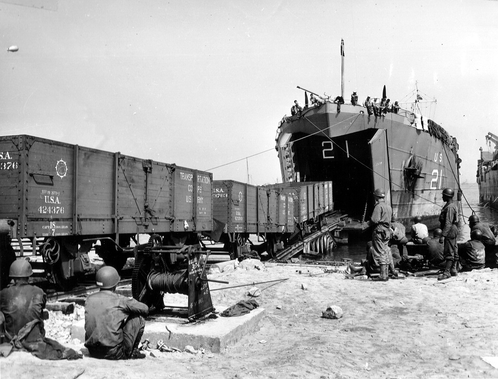
Left: LST 21 has arrived in Cherbourg, France. The LST is unloading train cars to be used on the French railway system, in July of 1944. Click for larger. National Archives
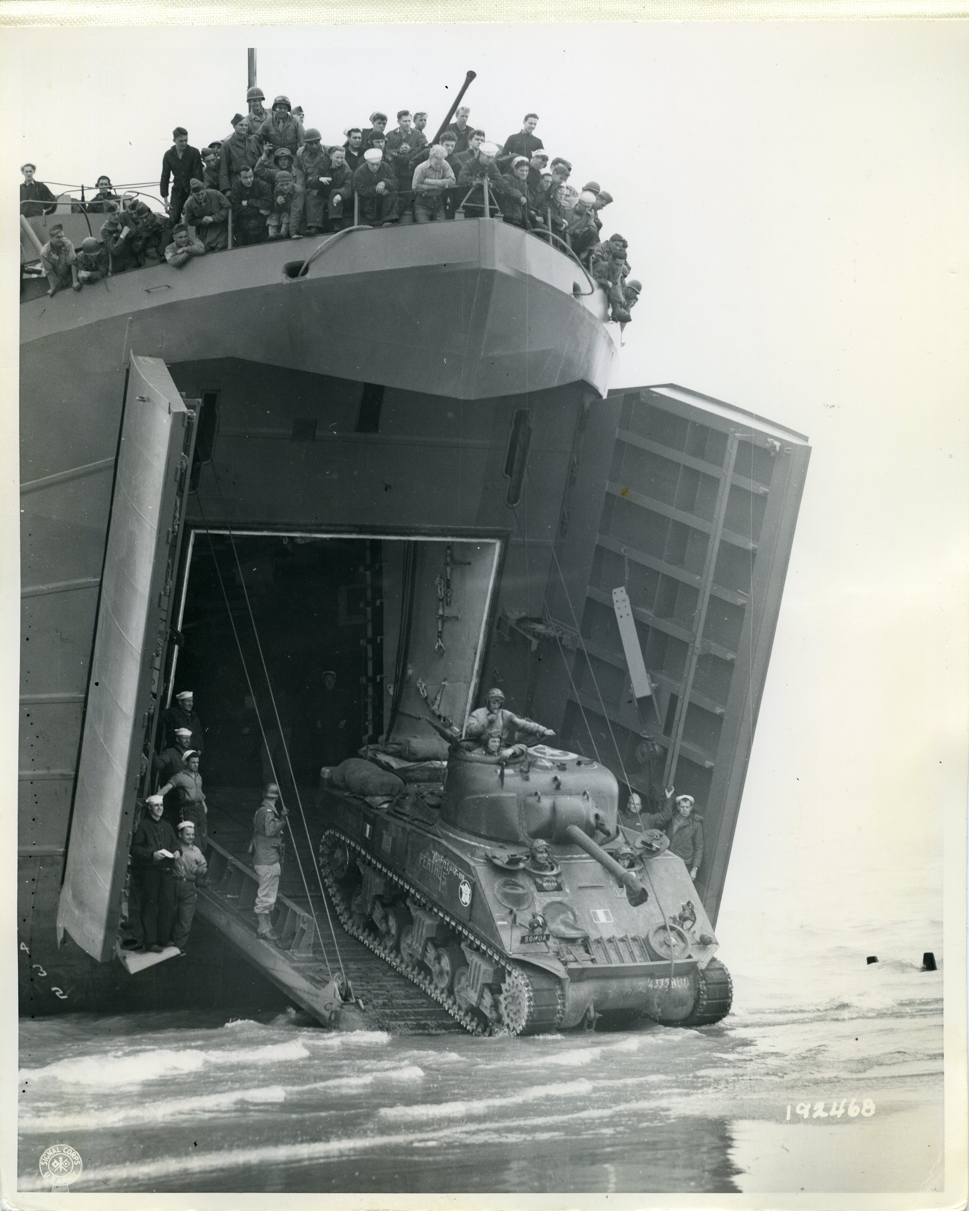
Right: 2nd French Armored Division tanks are leaving LST 517, going ashore on Utah Beach, in Normandy, 8/1/1944. Click for larger. National Archives
Thanks for reading! Please be sure to join us again in the next week or so for Part II, which will cover the LST engines in their second life after the war – powering tugboats and everything else. Part III will be on the “new” upgraded LST engine, the 567CA. Part IV will cover whole LST’s after the war, and a bibliography.
Be sure to check out the full series:
Part II – The EMD 567ATL: Part II, Repowers
Part III – The EMD 567ATL: Part III, The EMD 567CA
Part IV – The EMD 567ATL: Part IV, LST Survivors
Part V – The EMD 567ATL: Part V, EMD File Photos

THANKS FOR SHARING. I spent much on my time working on the 567A along with the 278A and the 268A , then later the 645 series. Great to see some of the amazing history
LikeLike
Paul – great post as always.
Chris
LikeLike
I just read that you are working up a 6-71 post, My web page (not a website yet) consists of images of my engineering 3D reconstructions of landing craft (and landing ships) of WW II. The types of armament, engines and machinery are also projects of their own. I have produced complete functional models of the 64HN/65HN/66HN family of Gray Marine engines, as well as the GM 6046 (twin 6-71 used in Sherman tanks) and 6051 (quad 6-71 used in LCI(L)’s). I have manuals for all of them. Do you need some material on any of the above? Please let me know.
I am very interested in the engines used in Landing Ships, GM and FM, and the manuals and drawings are very hard to find, but you seem to have several. Your posts are mind-blowing. I have been working up the LST’s, and the LSM’s are also in my list.
Thank you for your posts.
LikeLike