A couple of years ago, I wrote an in depth article on the Joe Hack designed tugboats Wana and Tamarin, built for Alcoa’s operation in Suriname. If you have not read it, then I urge you to follow the link below. This turned into one of the most viewed articles on this website. Be sure to read the comments at the bottom as well, from people who were there and knew these boats.
Unfortunately, I do not have too much to add. I was able to find another slide of the Tamarin, this time from 12/1970. Compared with the older images of her in the original page, not all that much has changed. A basic push knee was added to the bow, along with a spotlight.
The second find, was a 1954 video! This is a pretty basic home movie from the era, but its got some neat footage of the tugs, an Alcoa ship and the trip up the river. Click on the above image to take you to the internet archive link to watch it.
Again, be sure to visit the original post, linked at the top. I would still really love to know the final disposition of these two tugs. If by some chance anyone has any info, please drop a comment below or email me!
Forward: I originally asked Jay Boggess to put this post together to help better explain how AC power generation worked, as well as how EMD started down the path of AC technology. This will be important, as this year we will be taking a deep dive into EMD’s mobile and stationary power generation which were built around EMD’s first AC components: MH8 Highway Trailers, M16 Mobile Power Cars, S-Series Stationary Plants, MP Peaker Plants and more. The first one on the MH8’s will be in a few weeks or so. For now, lets take a look at AC power. Thanks Jay!
—————————————————————————
To turn the power of a diesel engine into movement in a tugboat, you need a propeller and a reduction gear. On land, in a locomotive, you need DC motors on the axles and a DC generator connected to the diesel. If you want to light homes and power factories with that same diesel, you need a generator – an Alternating Current or AC generator.
AC generators make 3-phase electricity to power our world of today. Go look at your nearest power line and you’ll see multiples of 3 conductors. That’s 3-phase electricity being transmitted from power plant to consumer. AC power is easily transformed from medium voltage at the generator (4160 to 24,000 Volts) to very high voltages (345 to 765 kiloVolts) for transmission across hundreds of miles, then reduced back down to low voltage (120 volts) to power our lights, air conditioning, water heaters, computers, television sets and beer coolers.
Sidebar: Is it a Generator or an Alternator? It’s both. An AC machine can be correctly described as a generator or an alternator. A DC generator is only described as a generator. When I was a small boy, my mom’s 1950s Ford had a GEN idiot light for when the ignition was on, but the motor wasn’t running. By the mid 1960’s, DC generators had been replaced by alternators and built-in rectifiers to make 12 volts DC. Thus, the ALT idiot light replaced the GEN idiot light.
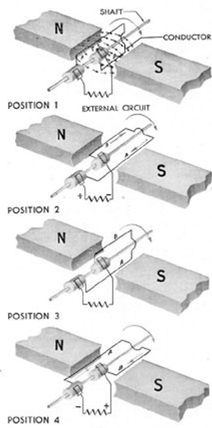
Any generator can be reduced to a fundamental basic – copper wires in motion breaking the lines of flux of a magnetic field. Let us first turn to how the US Navy explains it to new sailors in WWII – Figure 1:
In Fig 1 -Position 1, a loop of wire is set between the poles of a North and South magnet. The loop is connected by sliprings and brushes to the external circuit.
In Position 2, the loop is rotated so that it cuts the magnetic lines between the poles (the magnetic lines are essentially what attracts the two magnets together). When lines are cut, voltage is generated, a current flows thru the loop, thru the sliprings, thru the brushes and to the external circuit.
In Position 3, the loop is rotated more so that NO magnetic lines are cut, no voltage is generated and no current flows.
In Position 4, the loop continues and now is cutting magnetic lines again, but in an opposite direction of Position 2, so that the voltage is now in opposite polarity and the current flows in the opposite direction.
Figure 1 – Elementary AC Generator from Navpers 16162 – Submarine Electrical Systems
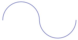
So now we have an elementary AC generator, making an alternating or sinusoidal output, like to the above. Let us morph this, slowly, into something that looks like a real electrical machine.
Here we have another excerpt from a different Navy manual – NAVSHIPS #250-660-2 Turbine Electric Drive – Basic Principles. Instead of stationary magnets, we will spin the magnets, below:
Here we have two electromagnets, one North and one South (think of the needles of your Boy Scout compass), energized with a battery through sliprings, supported by bearings, turned by a hand crank.
Now, we’ve added a coil that is stationary, so it’s called a Stator Coil. If we spin the crank, it will generate a voltage like this – an alternating voltage and when connected to a load, it will give us alternating current:
If we surround our loops of wire and field with iron (magnetic fields LOVE to flow through iron or steel) like so:
Then our generator is much more effective. Next, let us add two more loops:
This is now a 3-phase machine, like just about every other AC generator in the world. It makes a set of waveforms that look like this:
And is just about ready to connect to The Grid.
The electricity in your (North American or Brazil or southern Japan) wall outlet alternates at 60 Hertz (Hz). If we are in Europe or northern Japan, it would be 50 Hz. There are also other common AC frequencies; 25 Hz on the Amtrak Northeast Corridor electrification, 16 2/3 Hz on European railways and 400 Hz in aircraft. To make that 60 Hz in our little generator, we must spin the shaft at 3600 RPM. For 50 Hertz, it would be 3000 RPM.
But you ask, my big diesel engine won’t spin that fast! What do I do? Simple – add poles to your AC generator. The formula for 60Hz output is: RPM = 7200 / # of polesOR
Number of Poles RPM 2 3600 } – typical rpms for a coal or nuclear steam 4 1800 } turbo-generator 6 1200 8 900 10 720 12 600 14 514.2 16 450 18 400 20 360 24 300 30 240 60 120 } – Grand Coulee Dam on the Columbia River 84 85.7 } (where the author worked) had hydrogenerators 100 72 } that ran at these rpms
Sidebar – What is a Hertz? A Hertz or cycle per second – a measure of frequency and is named NOT for a rent-a-car company, but for Heinrich Hertz, a German physicist . It is the number of reversals per second in an electric circuit or really, of anything. To hear 60 Hz, put your ear to an outdoor transformer. If you fly in an airliner and plug in your headphones to watch a movie, you can hear 400 Hz noise in the background.
Figure 3 – Grand Coulee Dam G18 Rotor, Jay Boggess photo.
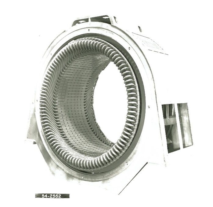
And this is the stator for the rotor above:
Figure 5 – Grand Coulee stator – 125 MVA, 120-RPM from 2010, Jay Boggess photo.
The A11 stator has a bunch more coils than our simple 3-coil machine: 96 to be exact. Because there are 10 poles in the rotor, there must be at least 1 coil per pole for phase (that would be 30 coils) but here, our 1954 EMD engineers picked 96 coils, or 3.2 coils per pole per phase.
THREE point TWO??? That’s a confusing number! And it was confusing to me as a young EE at EMD in the 1980’s. It works out that the electrical engineers wanted a high-voltage machine, so all those coils (32 per phase) were wired in series, daisy-chaining around the perimeter of the stator. The old-timers also wanted a pure 60 Hz sine wave voltage output as well, without any 3rd, 5th, 7th, 11th or 13th harmonics to cause heating and noise. By simply having 3 coils in series next to each other instead of one big coil, that emphasizes the 60 Hz fundamental frequency and suppresses the higher harmonics. In the same way having 3 coils under some poles (remember there are 10 poles total) and 4 coils in series under other poles adding up to 32 coils per phase also improves harmonics.
Since this is the mid 1950’s EMD 567 engines ran from 700 to 800 RPM at full power, so the 10 poles would give a 60 Hz speed of 720 RPM.
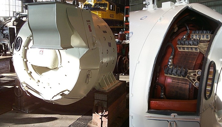
The whole machine put together in the EMD Engineering Test Stand looks like this:
Figure 6 – A11 synchronous generator (right) in test stand – 1000kW, 2400/4160 Volt in this 1954 photo. On the left a D32 DC generator is used as a motor to spin the A11 for testing. Your author used this same test stand in 1980s to test the main generators for the SD60 and SD70MAC locomotives. Jay Boggess collection.
Here is a cross section of that same machine:
Figure 7 – A11 Generator from EMD Specification 7107 GM Series 567C Mobile Power Car – Paul Strubeck collection.
Cutting The Sausage
In the 1950’s, EMD built 4 different industrial generators: the A5A, A7, A11 and A15 for 500-750-1000-1500 kilowatts (kW), all at 2400/4160 Volts.
# of poles
kW
kVA
Amps Y
Weight-lbs
A5A
10
500
625
87
9,170
A7
10
749.6
937
130
11,140
A11
10
1000
1250
174
13,260
A15
10
1500
1875
260
16,550
All were 60 Hz at 720 engine RPM. They were all the same diameter and vary by how long the stators are. The differences in weight signify the difference in stator length. So, we have shorter machines for lower kW generator ratings.
How does the design vary as the kW capacity changes? This is where we cut the sausage. All things being equal, the voltage produced by the machine is proportional to the number of turns in each coil and the length of the stator core. The 96 coils of the stator have different number of turns per coil, depending on which size machine we’re talking about. The A11 most likely had coils with 6 turns each. We also know that its core is 17 inches long and thus 6 times 17 inches is the “voltage factor”. If we want to make a shorter machine, then we increase the number of turns per coil to make the voltage factor the same.
How do you know/find the “right size” engine for the desired generator? The generator does not care. You can attach the A11 to a little 8-cyl 567, the generator will be loafing along, running fine, but at a waste of materials – steel and copper not needed. Attach the A5A to the 16-567 and run it to 1000kW…the coils will melt.
So, really, the generator is designed to fit the engine. 1000kW and 720 engine rpm. 720 rpm means 10 poles for 60Hz. 1000kW at 0.8 PF means 1250 KVA. 1250 kVA and 4160 volts means 174 amps. The 174 amps sets the coil current capability. The turns in the coil set how long your steel stator sausage needs to be. Viola! You have just about designed your AC machine.
Getting the Power In and Out of the Generator
We can think of both AC and DC generators as both a converter (taking the mechanical energy of a spinning shaft and turning it into electricity) and an amplifier (taking the 10’s of amps in the field circuit and translating that into a thousand amps of electrical power). For a DC generator, the field circuit is stationary, and the power circuit rotates. For the AC generator, it’s the exact opposite.
Figure 8 – D32 Main Generator (left) and its commutator and brush rigging (right) from an MP15DC locomotive. Anchorage, Alaska 2007. Jay Boggess photos.
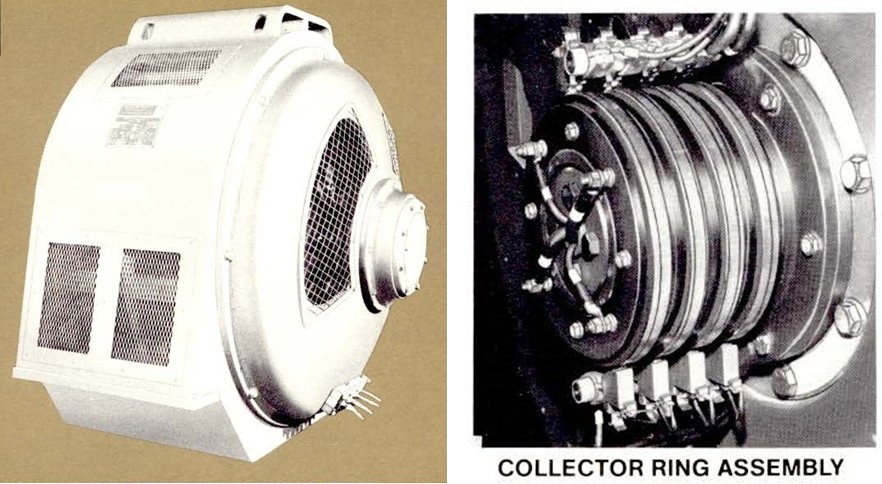
Figure 9 – A11 AC Synchronous Generator & AR10 Collector Ring Assembly. Adapted from EMD pamphlets – Preston Cook collection.
In Figure 9, the output emerges from the terminals highlighted by the yellow arrow – 4,160 Volts, 187 Amps and 1,250 kVA. And it is all from the stationary stator. The power to the rotating field goes thru the collector rings on the right – 65 Amperes excitation for 5.2 kilowatts. It’s much easier to move 1,250 kVA of electric power through stationary connections than move 1050 kilowatts through a rotating connection.
AC Generator Excitation
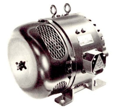
Another difference between AC and DC generators is that while it’s easy to make a DC generator self- exciting, an AC generator requires some sort of external exciter. The A5/A7/A11 generator series used a small DC generator (often called an exciter) to provide the power needed to excite the AC generator (as seen in Figure 9B). This exciter would be driven by the diesel engine cam shaft or by a belt from the main generator.
Figure 9B – Delco 120V, 10KW DC excite generator. Adapted from EMD pamphlet – Preston Cook collection.
Modern AC generators can use semiconductor power electronics to eliminate the rotating exciter completely, or use a small “brushless” exciter mounted on the generator rotor to do away with the collector rings and carbon brushes completely, but at the expense of slower transient response.
Synchronous Generator. – what does that mean?
Whether they be motors or generators, there are two basic types of AC machines. Induction or Synchronous. Induction machines (which are usually motors but can be generators) have a rotor with no electrical connection to the outside world. Synchronous machines (usually generators but they can be motors) DO have an electrical connection OR in the modern age, permanent magnets, into the rotor.
Induction machines rotate at a little bit more or less than synchronous speed – say 1780 rpm for a 4 pole, 60 Hz induction motor. A 4-pole synchronous machine will run at EXACTLY 1800 rpm. For different synchronous speeds, the designer picks a different number of poles.
How the A11 begat the AR10 of 1965
In the early 1960’s, EMD had just about run out of what they could do with the DC main generator. The GP35/SD35 squeezed 2500 horsepower out of the D32 DC main generator but at a cost of immense power circuit complexity. To go any higher in horsepower would mean a completely new DC machine. Instead, the silicon semiconductor came to the rescue. By marrying an AC generator (which EMD already had in the A11) with the emerging silicon rectifier diode (this can be expanded at a later date if anyone is interested), the higher horsepower of the 16-645 turbocharged diesel could be supported.
There were some major changes to take the 4160-Volt A11 AC generator into the 1000-Volt Alternator-Rectifier AR-10 traction generator. Instead of all the coils wired in series in the A5/7/11/15 models, much higher current was needed. So the stator was dramatically redesigned from 96-slots / 1 parallel to 90-slots/10-parallels .
And this is the stator for a 10-pole / 90-slot / 10-parallel AR10 machine:
AC Power is a lot like beer in a mug. You have the golden lager on the bottom, the foam on top and the mug which contains them both.
The beer itself is what you want, it’s what gets things done, this is equivalent to the kiloWatts or Real Power. This accomplishes work; it pumps water, it can heat your cold water into hot water, it can run your air conditioner, it is what you pay for at the end of the month on your electric bill.
The foam just gets in the way, this is equivalent to kiloVARs or kilo Volt Amperes Reactive or Reactive Power. It takes up space in the mug, it’s a result of either pouring the beer too fast or in electricity, the act of running an induction motor. Electric heaters don’t make foam, they just consume beer.
KiloVoltAmpere is simply the size of the beer mug. This is Apparent Power or KVA for short. It’s what we must size our generators, cables, power lines and transformers to reliably handle. For a given-size mug, the more foam the less lager, so it behooves us to not have too much foam or find a way to get rid of the foam.
Induction motors make foam, or more technically put, they have a lagging Power Factor. As you might gather, Power Factor is the ratio of Real Power to Apparent Power, and it varies from 1.0 (for a water heater) to 0.8 (for a typical induction motor) all the way to 0.0. Capacitors connected to the power line will absorb the foam produced by induction motors. Also, a synchronous generator can also absorb foam or make foam of their own, if necessary. A synchronous generator not connected to any turbine or diesel is called a Synchronous Condenser (condenser is another word for capacitor that our German friends love to use, or the “points and condenser” that our fathers would change during an engine tune-up back in the 1960’s). Synchronous Condensers can be used in many places in the grid to stabilize the voltage and absorb or provide VARs as necessary.
Figure 11 – Synchronous Condenser installed at the AEC Portsmouth Gaseous Diffusion Plant – from the www.portsvirtualmuseum.org website.
The picture above is of a synchronous condenser of the Portsmouth Gaseous Diffusion Plant, which had THOUSANDS of induction motors to run the compressors that ran uranium hexafluoride thru THOUSANDS of “converters” to separate U235 (what you build bombs and reactors with) from U238 (not good for much). It is essentially an AC turbo-generator without a turbine. It is encased in a vessel filled with hydrogen gas (H2 acts as a low-wind-resistance coolant through the windings) and spends all its life absorbing the inductive foam that all those induction motors make by simply running.
Unlike the Lager/Foam/Glass of the beer analogy, in 3-phase power, there are right triangles and Mr. Pythagoras involved. For a 1000kW/1200HP induction motor, the right triangle looks like this:
Our 1000kW motor makes 750kVAR while running, which when you solve the right triangle means that everything has to be sized for the 1250 kVA. BUT, since the boys at Portsmouth had all those Synchronous Condensers absorbing all those 750kVARs, the power lines and everything feeding the plant only had to be sized for the 1000kW of actual, real-power load.
In a similar way, the A11 AC generator could support the 1000 kilowatts the diesel engine could put out (1000 kW is about 800 hair dryers turned on at once) but had to be designed for 0.8 or 80% power factor to support the “foam” of induction motors that might be connected to its terminals.
So, we can either overdesign the generator to make room for the foam or use capacitors and synchronous condensers to absorb the foam induction motors create. Thus, we can fill the mugs closer to rim and enjoy more beer with less foam.
Jay Boggess PE former EMD electrical engineer retired USBR supervisor 12-Dec-2024
Author’s Postscript: Though 40 years of engineering, I want to thank many folks living and dead that I’ve learned something about electric machines from.
From EMD: Forrest Green, Scott Given, John Madsen, Jim Hibbard, Jack Carter, Bob Lis and my long-time boss Bob Becker.
From US Bureau of Reclamation: Jim Bussell, Eric Eastment, Nate Myers, Jerry Robinson, Mike Schuh (for the beer foam analogy), Darryl Liscomb and to an array of non-electricals who asked questions and forced me to provide digestible answers.
And finally, blogmaster Paul Strubeck for asking me to write this and to Doug Ellison for being another one of those non-electricals to ask questions and prompting me to have fun and explain things.
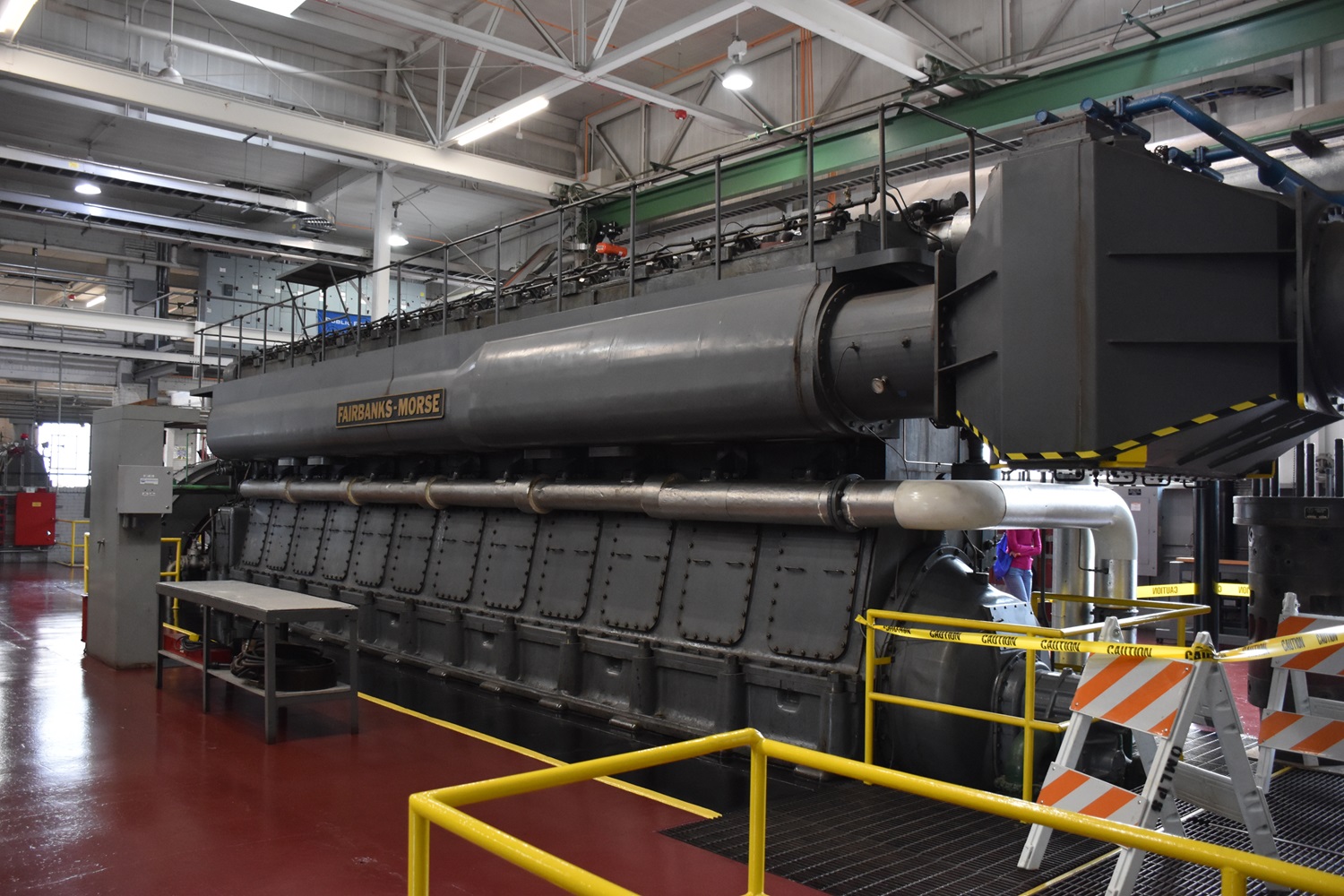
Southwest of Cleveland, Ohio is the small town of Oberlin, home of Oberlin College. Like many small towns of the era, a small municipal power plant was built in 1933, utilizing a quartet of Fairbanks-Morse engines.
The Oberlin plant was featured the January 1948 issue of Fairbanks-Morse News. The plant originally featured 4 FM 33 engines: a 6 cylinder 33F12, a pair of 6 cylinder 33F16’s and a single 7 cylinder 33F16. In 1948 the first Opposed Piston engine was installed, which is still in place today. The plant was expanded in 1957 with the addition of the first 31AD18.
Last year, Jay Boggess was in the right place at the right time, and was in town for the powerplants annual open house and was able to take and share a slew of photos. Lets take a walk through the plant and look at each of the engines. Click on all photos to view larger versions.
Engine #1 This is the original 38D 8 1/8 OP engine installed in 1948. This engine is most likely a WWII surplus engine, and is an “off the shelf” OP engine. The engine has the stock 1600HP rating, and is the only FM engine in the plant that is not dual fuel capable. Engine #1 can produce 1136kW.
This 10 cylinder OP was installed in 1948, and is a pretty run of the mill powerplant engine of the day. FM would supply their own generator as well. These 10 Cyl. OP engines replaced a lot of older 32E and 33F engines across the country in the 1950’s.
The right, or control side of the engine. FM OP’s have a very simple “Run – Stop – Off” control lever to operate them, however there is a slew of linkage’s inside that connect it all together.
Looking at the front of the engine, you can see the exhaust risers coming out of the engine, wrapped in insulation. Those FM exhausts throw off quite a bit of heat. An oil filter is on the floor in the foreground.
Unfortunately, FM, like many other engine companies did not add dates to their builders plates. While the serial number does match a 1948 built engine, it was not uncommon for new numbers to be issued on war surplus equipment.
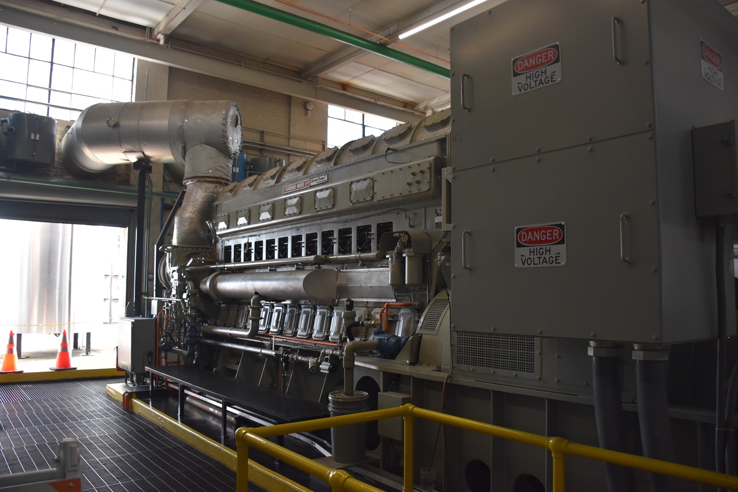
Engine #2 & 3 These are two sister FM 38TD 8 1/8″ OP engines installed in the plant in 2000. While based on the original FM 38D OP (like engine #1), these are the modern equivalent. They are dual fuel, thus they can run on straight diesel, or natural gas using diesel as a pilot fuel. These OP engines are rated for 3165kW each, and usually around 3600HP, thanks to the dual turbochargers.
While deep down these engines are the “same” as the original OP design above, they have a slew of modern upgrades in fuel, exhaust and emissions systems.
While FM once made their own generators in house, they now use outside suppliers, in this case, these were built by Baylor Motor/Generator group. Note that these are mounted on large skids.
A good look at the twin turbos on these modern OP engines. Imagine one of these in a fleet submarine? The turbos feed into a large intercooler before entering the airbox.
Along with the upgrades mentioned, these higher HP OP engines also run a lot faster – 900RPM. Note the expansion tanks mounted on the plant wall, just to the right of where the exhaust exits the building.
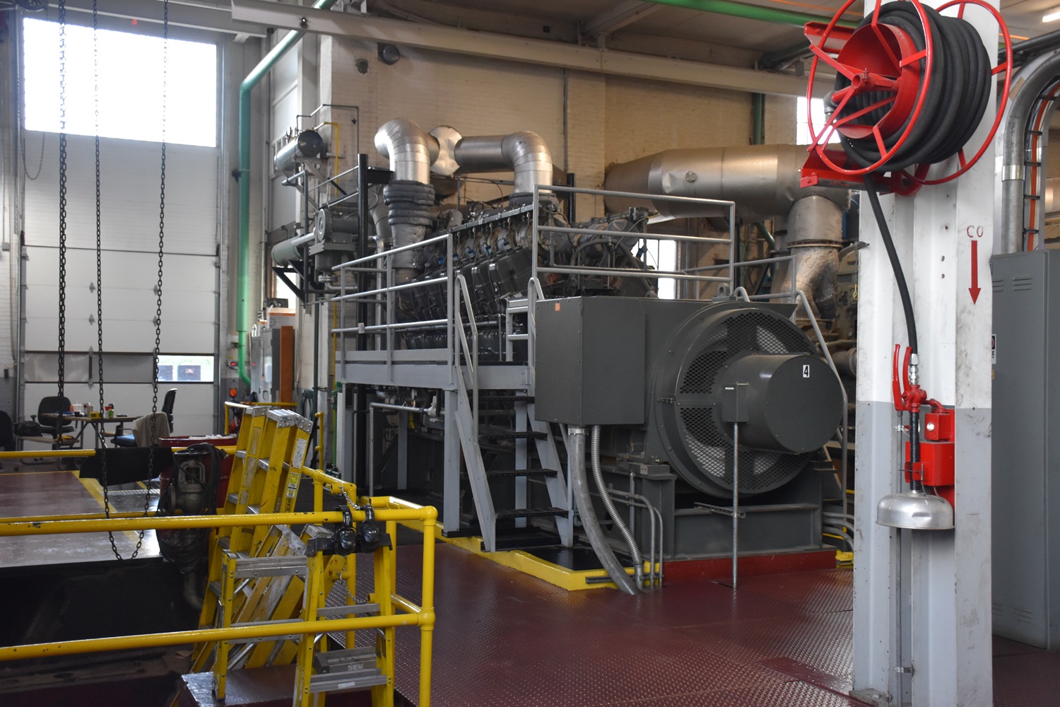
Engine #4 The newest engine in the plant is a Waukesha 12 Cylinder AT27GL installed in 1997. I will be the first to admit I know absolutely nothing about these engines. Waukesha Motor Company was founded in 1907, and produced a line of gasoline and diesel engines. By 1955 the company was producing smaller engines for everything from airport snowblowers to small powerplants. The engine in the plant is a model that was introduced in 1985, when the company was under ownership by Dresser Industries. This engine runs on natural gas only, and is rated for 2100kW. The engine features twin turbochargers, and has a metric bore and stroke – 275mm x 300mm (10.83″ x 11.81″).
For a V engine of this size, the AT27GL is still a rather compact package when compared to the Cooper Bessemer LSV.
Note the bedplate for former engine #5 in the foreground. I will do some more homework on these engines down the road.
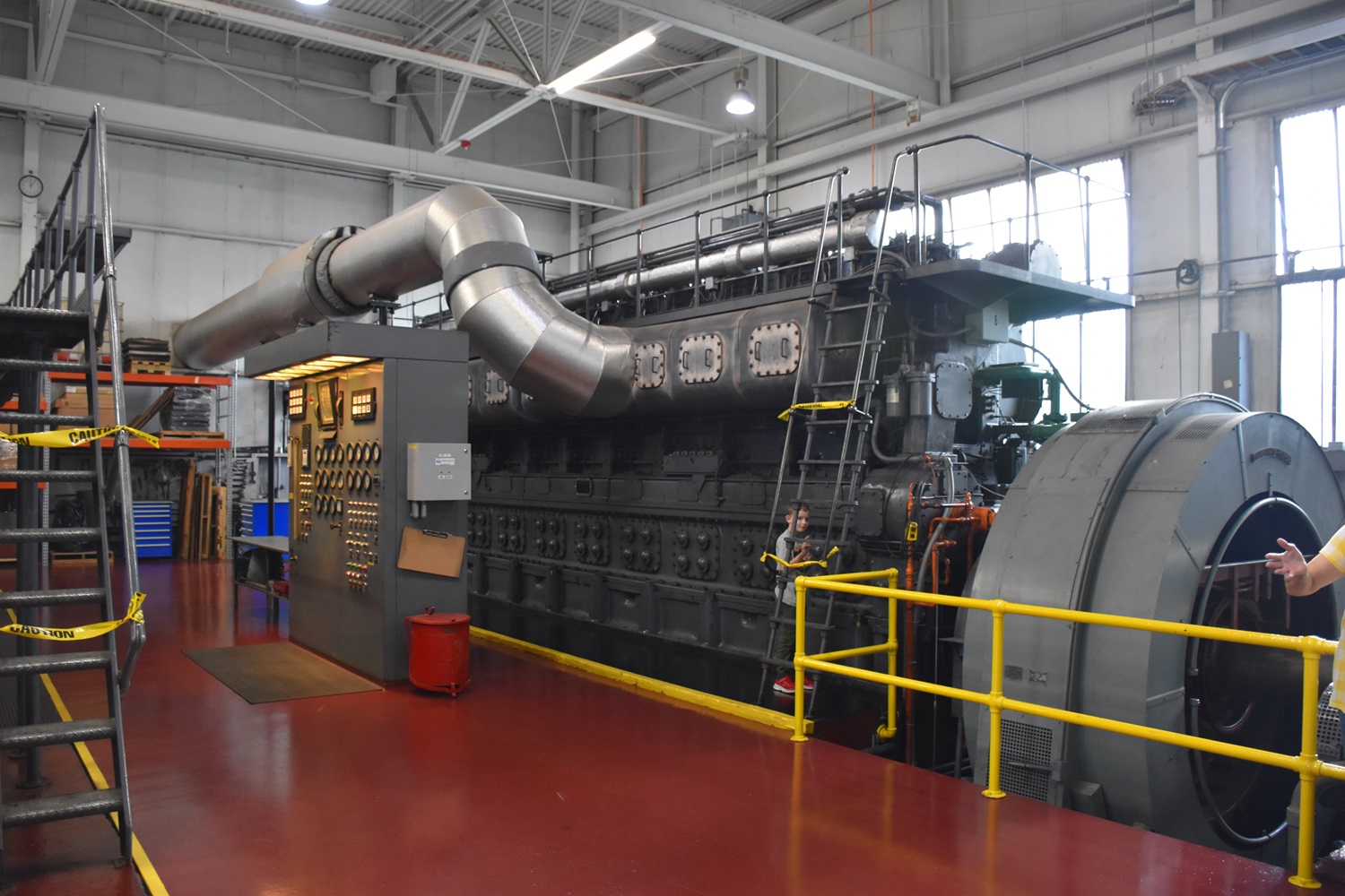
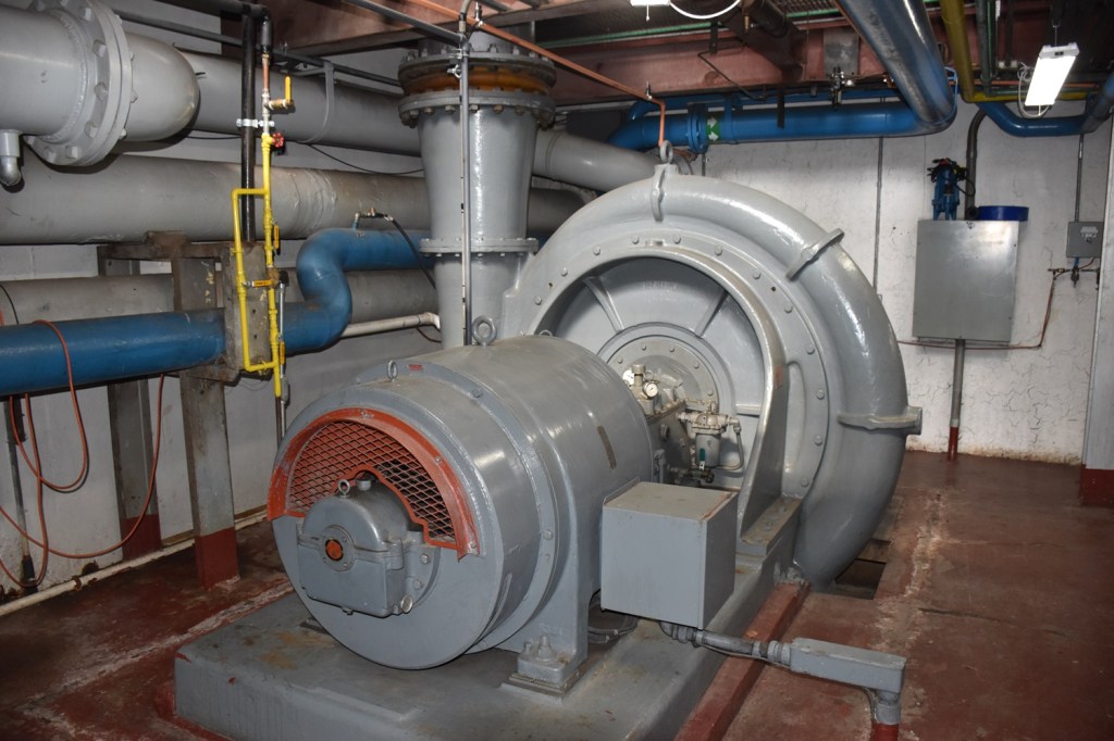
Engine #6 The first engine in the newly expanded plant is an FM 10 cylinder 31AD18. I wrote more about these engines on these two pages here and here. This engine is rated for 2500kW at 3500HP.
The right side of the engine. This is the air intake side. Note the oil pump located at floor level. The jacket water cooling line is coming up out of the floor. The oil pump is the only attached pump on these engines.
This is the 24″ air intake pipe coming up out of the floor, supplied by the Roots blower seen a few photos down.
A look at the data plate on this FM built alternator.
The left side of the engine, which also houses the gauge and alarm panel.
Looking up at the right side of the engine. You can see the engine control lever just below the green oil line.
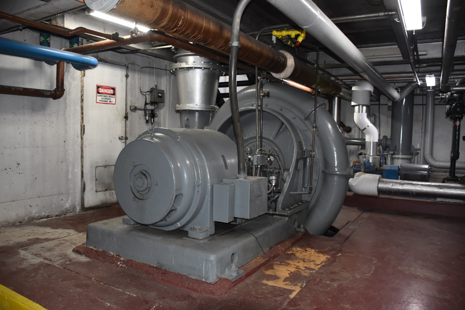
Above – The FM 31A18 engines almost always used an external, Roots centrifugal blower to provide scavenging air (they are two stroke after all) for the engines. This blower moves 17,700CFM.
Left – Engine #6 has been upgraded with a more modern gauge and alarm panel, likely tied into a computer interface.
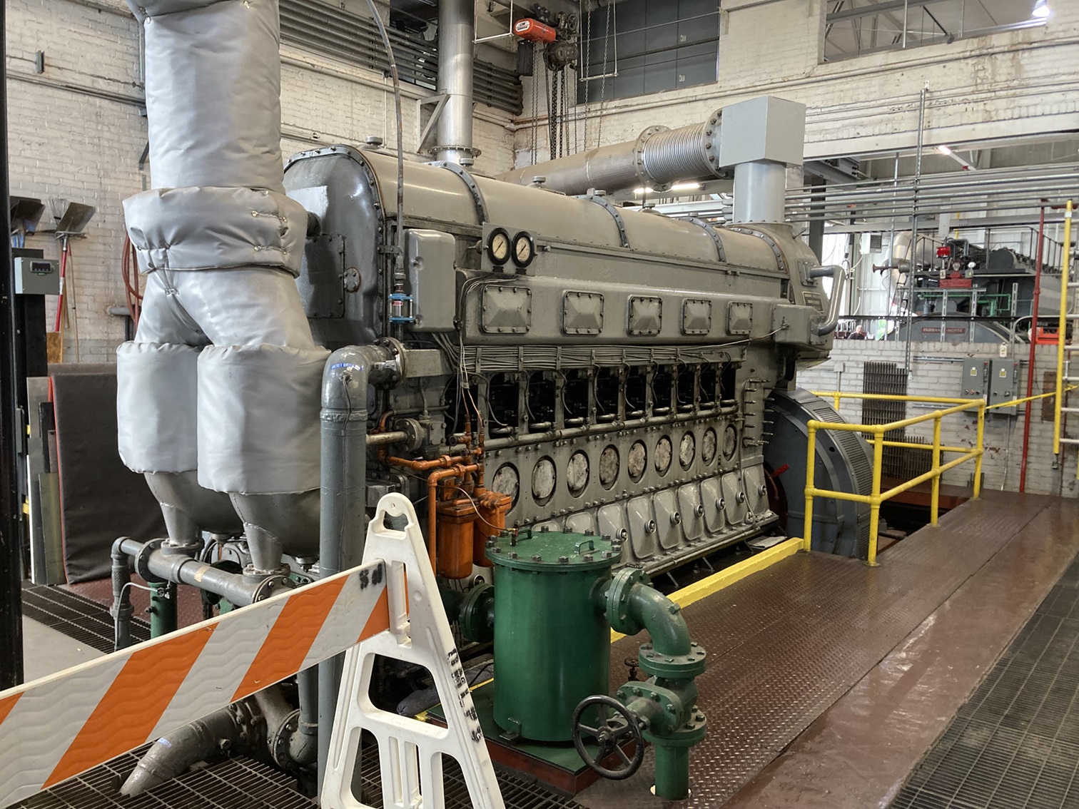
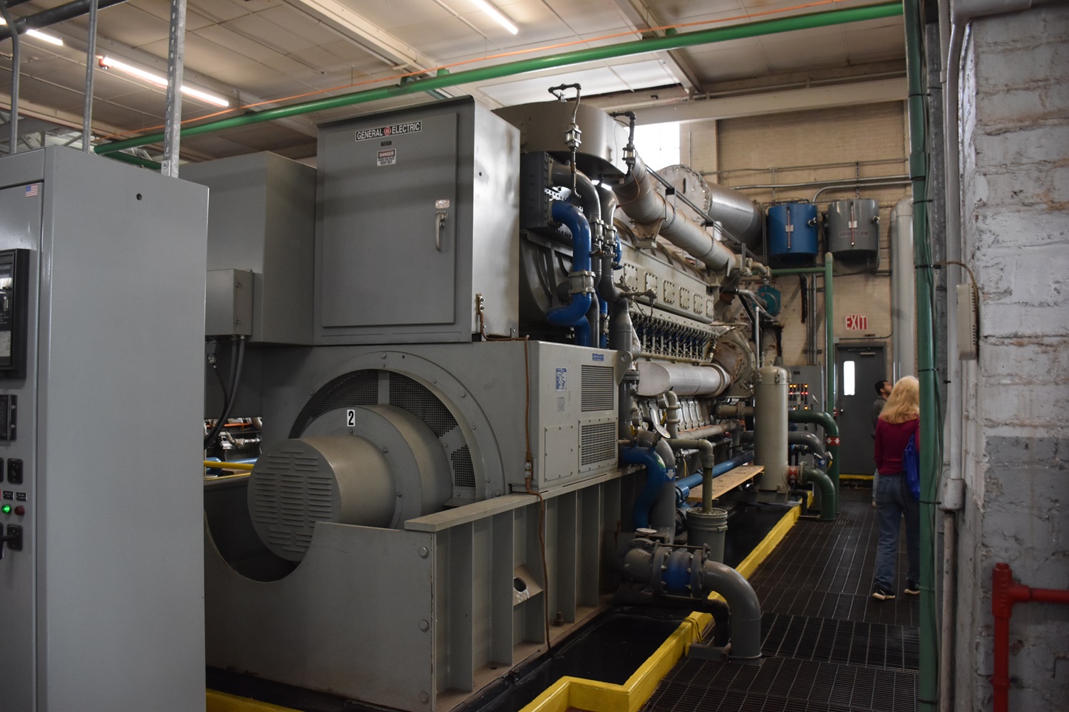
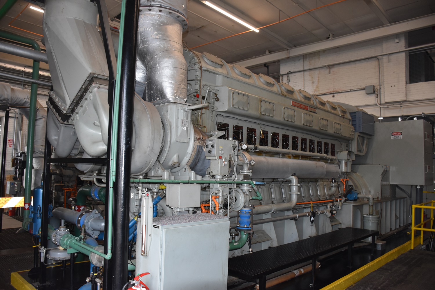
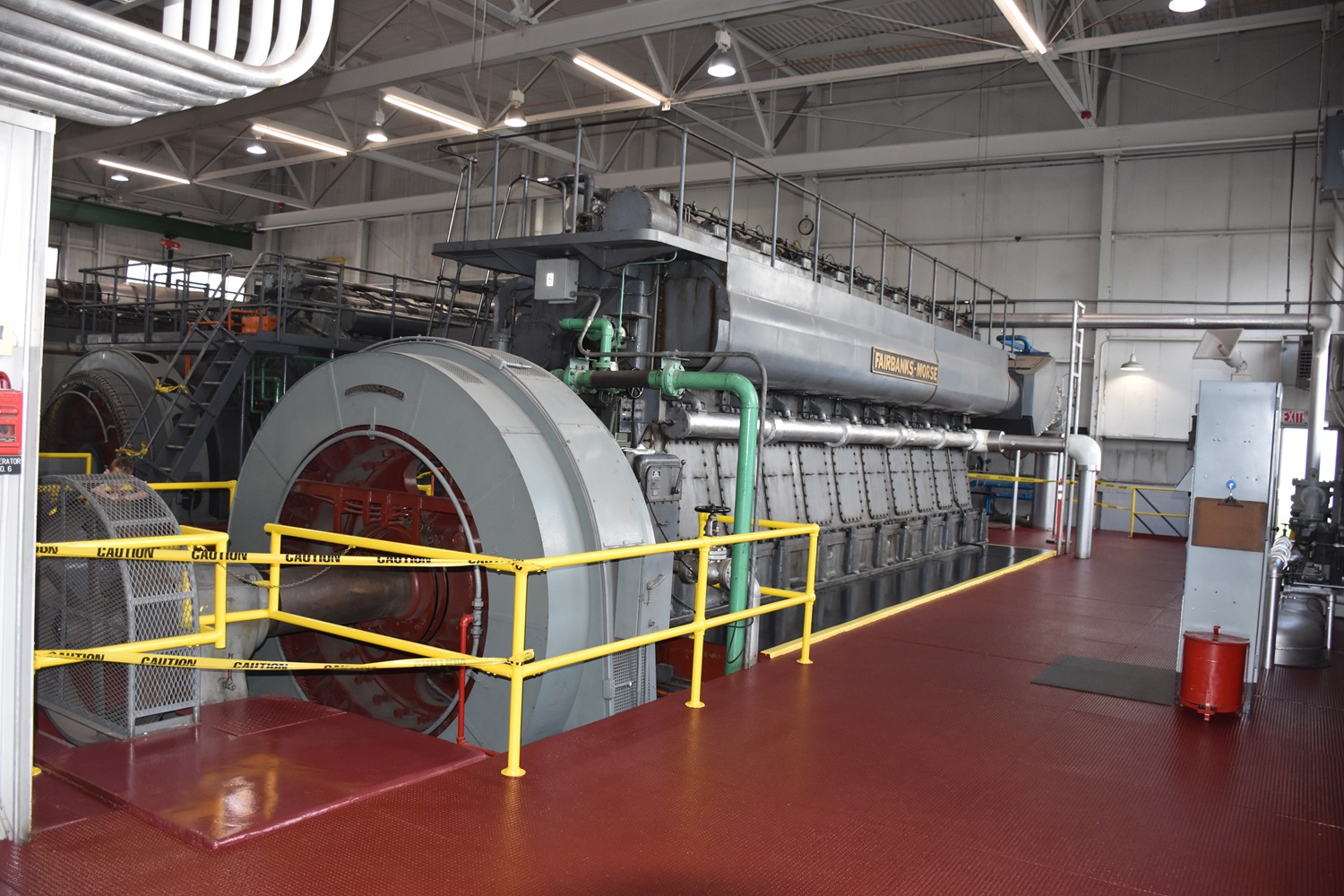
Engine #7 #7 is a Cooper-Bessemer 16 Cylinder LSV16GDT. The turbocharged 4 stroke LSV engine features a 15 1/2″ bore and 22″ stroke. Like the big FM’s, the Cooper-Bessemer engine is a slow speed, running at only 320RPM, but makes 3710HP and 2650kW with a GE alternator.
The Cooper-Bessemer LSV platform became a very common municipal powerplant engine in the 1950’s, and were being installed well into the 1980’s and later throughout the country, and are still common today.
A General Electric 2600kW AC Alternator was used in this specific application.
Left side of the engine. The turbocharger is centrally mounted on the above left side. Along with power generation, Cooper-Bessemer made a large line of natural gas pumping engines.
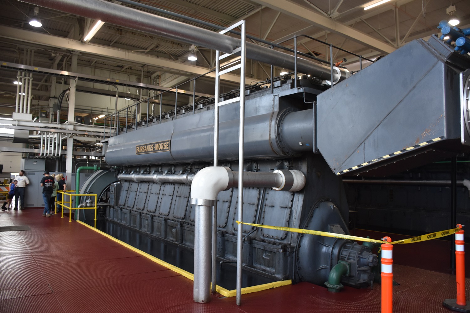
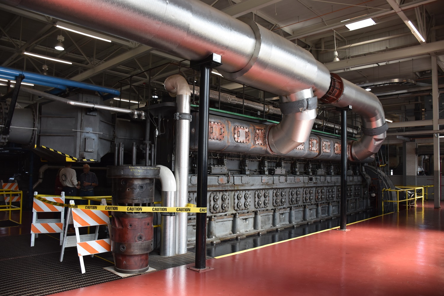
Engine#8 Engine #8 is another FM 31A18 – but this one is a 12 cylinder. This huge engine produces 4200HP and 3300kW, only slightly more than the more compact OP engines above, however operating at a much slower speed.
The gentleman on the left provides a sense of scale as to how big this engine actually is. This setup would be FM’s largest, successful production engine, with numerous 31A18’s still running around the world. Not bad for an engine that has not been built in 50+ years!
The generator and belt-driven exciter. Note the polished floor – municipal plants are almost always kept in top shape!
The exhaust side of the engine. A lot of times, the exhaust would be run into the floor, and run outside in a concrete conduit, however these exhaust through the plant wall into the mufflers.
Like engine #6, this one also uses the Roots blower mounted in the basement. Be sure to read Jays post on the history of Roots here.
The right side of the engine. I am not sure what the large box is on the intake side of the engine, possibly a filter housing – I have not seen it on another 31A18.
Data plates on the FM built alternator. FM was once a powerhouse in not only engines, but generators and motors as well.
The data plate on the blower. This one providing a little more (21,000CFM) then the one used on the 10 cylinder engine.
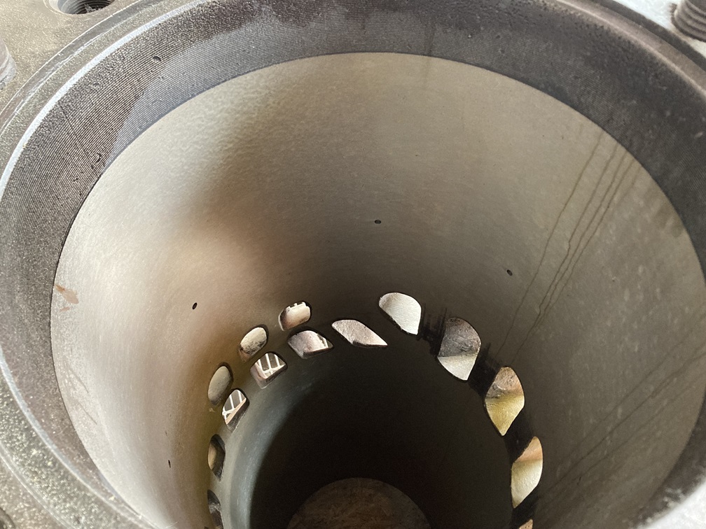
Its not super common for municipal powerplants to have lots of spare parts on hand, as most of the heavy repair work is mostly contracted out these days. Oberlin does have some though for the FM 31A18’s however.
A row of pistons, connecting rods and cylinder liners lined up against the wall.
Looking down into the bore of the liner showing the intake and exhaust ports.
Some of the plants electrical switch gear.
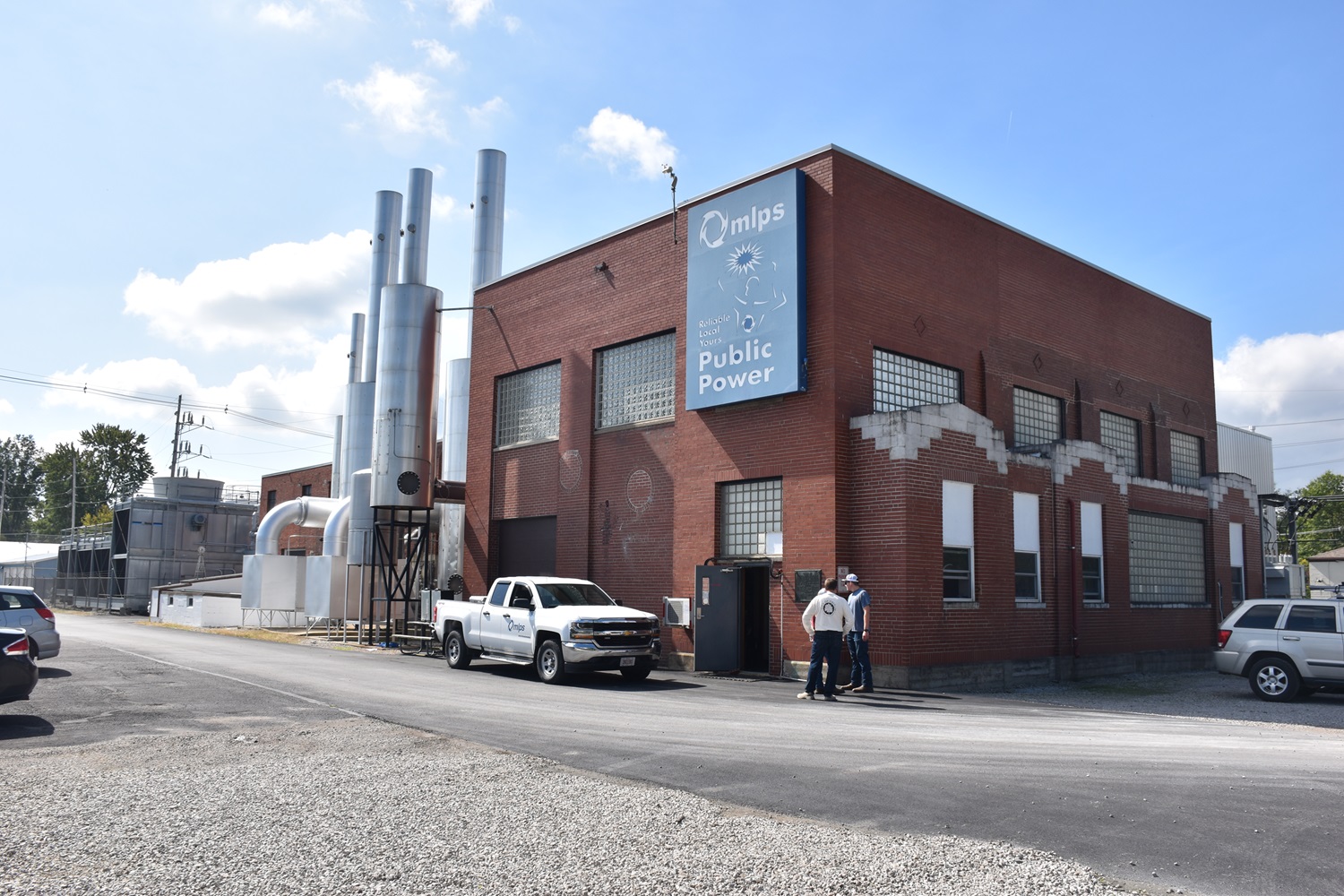
At some point (possibly during the first expansion), a small addition was added to the left side of the plant – this is where the #5 engine originally was, however I do not know what that engine actually was.
Compare this view, to the one in the FM news issue on the top of this page, you can see the small addition they added. Whoever did it should be proud, because it matches perfectly! You can see one of the cooling spray towers in the back.
The mufflers for the 4 engines in the original part of the plant. On the left is the original FM OP #1 engine, the two bigger OP’s in the center, and the Waukesha on the right. The smaller boxes towards ground level are the air intakes.
The newer part of the plant features more spartan steel construction, versus the ornate brickwork of the original.
These mufflers are for the two FM 31AD18’s, and the Cooper-Bessemer in the middle.
Thanks to Jay Boggess as always for sharing these photos!