By the early 1990’s, the Great Lakes Towing Company (GLTC) would have the only running Cleveland 498 engines left in the US (See note on the bottom). The Towing Company as they are known has a rich history dating back to its formation in 1899, consolidating several smaller tugboat companies on the Great Lakes. GLTC currently serves numerous ports across the Great Lakes, and is the largest user of Cleveland 278 (A and non A engines) left in the country.
Starting in 1907, the company began to build their own tugs in house, in their own shipyard. The yard, originally in Chicago, and moving to Cleveland is still churning out all new tugs for the company today, as well as doing outside work.
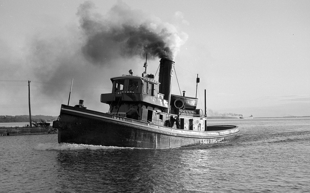
In 1931, the yard constructed Hull # 67, and named her the Idaho. GLTC had two sizes of tugs, the smaller, “Type I”, which were named after cities, and larger “Type II”, named after states. The Idaho would be the last new tug built until 2008.
The Idaho was originally powered by a single cylinder, 26″ x 28″ steam engine. The tug was 84′ 4″ long, 20′ beam and a 12’6″ depth. The tug was one of three that would receive a raised height wheelhouse for doing lake towing.
The Idaho after receiving her raised wheelhouse. Please note that this photo is not in my collection, simply one from my files. If anyone knows the photographer or archive please send me a message so it can properly be credited.
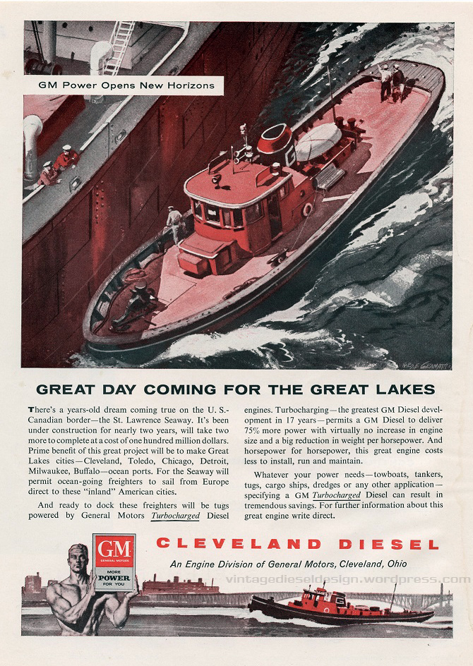
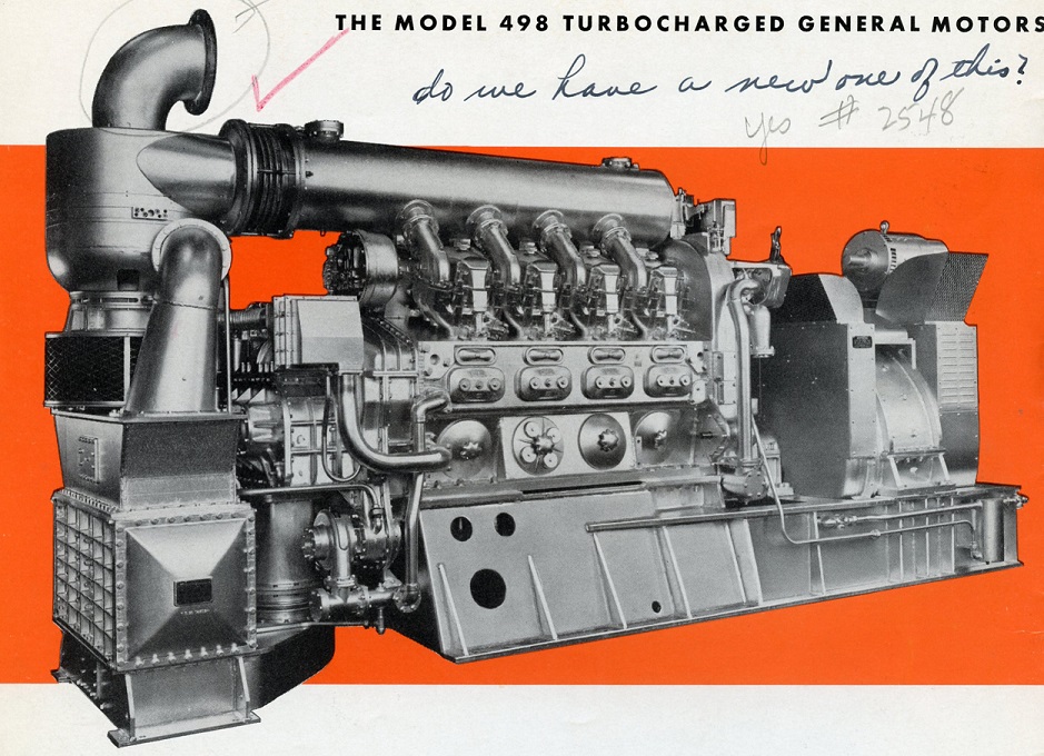
Ironically, one of the very first pieces of Cleveland Diesel ephemera I would add to my collection would be one depicting the new 498 powered tugs of the Great Lakes Towing Co.
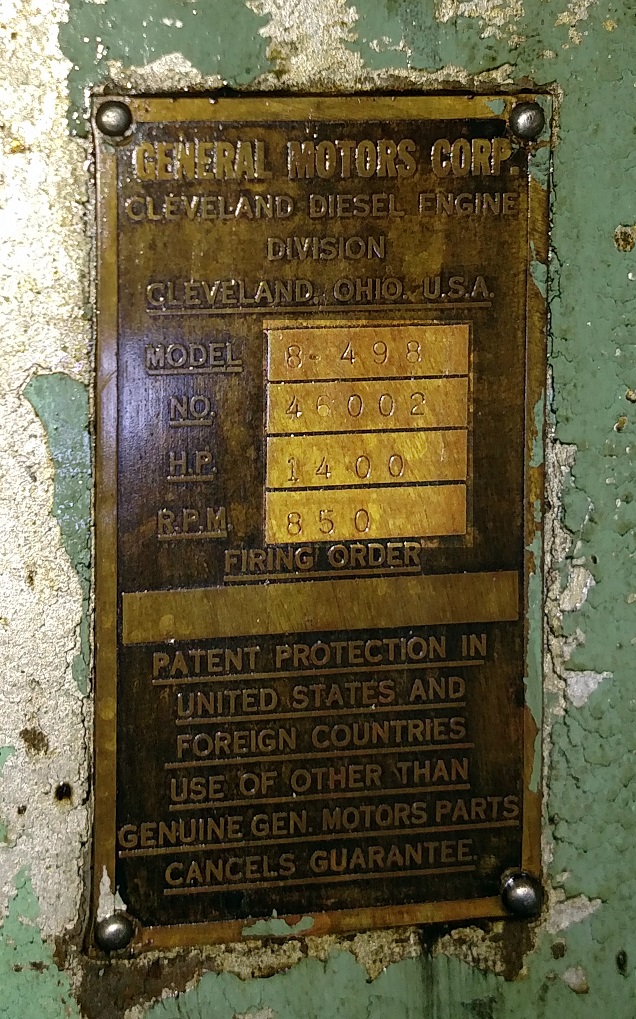
In 1956, the Idaho was on the block to be converted to Diesel propulsion. The engine chosen was the new 498 from Cleveland Diesel, as outlined in previous posts. Cleveland Diesel Order #1640 was placed in early 1956, for a pair of left hand rotation, 1400HP, 8-cylinder 498 engines to convert the tugs Montana and Idaho (Montana was an identical sister, Hull #60 of 1929). The engine for Idaho, #46002 was shipped from the factory on 12/13/1956, having to only go a few miles up to the companies shipyard. The tugs would receive Diesel-Electric propulsion packages, utilizing WWII surplus Destroyer-Escort main generators and propulsion motors. Disaster struck the Idaho shortly after being rebuilt on 10/21/1960. The tug was assisting the lake ship C.H. McCullough, Jr. in Chicago, when the tug was sunk. She would be raised, dried out and put back in service. A photo of her being raised appears in Alexander Meakins “The Story of the Great Lakes Towing Co.”
The 498 powered tugs would never stray too far from the main yard in Cleveland, typically working the ports of Cleveland, Ashtabula, Toledo or Detroit. The porthole aft of the wheelhouse is the tugs small bathroom. Photo by Isaac Pennock.
Great Lakes Towing Company would ultimately have a quartet of 498 powered tugs. The Diesel-Electric Montana and Idaho, and the Clutch tugs Tennessee and Pennsylvania which were converted in 1960 from Steam. Montana would be retired in 2006, Tennessee in 2012 and the Pennsylvania in 2019. Ironically, the Pennsylvania would wind up receiving a replacement engine at some point in her life, originally out of the towboat Leila C. Shearer. This too was replaced with an EMD 12-645, however the conversion was never finished.
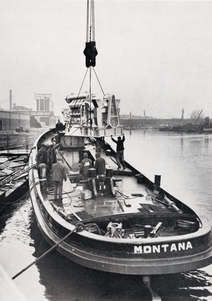
Sister tug Montana received the first 498 engine to be sold, seen here being lowered into the tug at the Cleveland yard. From Cleveland Diesel’s “More Power For You” brochure.
Noting that the last surviving 498 was likely nearing the end of her life, we reached out to the company to see about the possibility of documenting the engine and tug, and maybe see about preservation options. Unfortunately, we would be a touch too late. While the tug was still around, it was sitting laid up having suffered a catastrophic engine failure in 2016, however we were welcome to document her anyway.
The tug was laid up in Detroit for a few years, and was being used for parts for the other tugs in the GLTC fleet (while the engines were different, the tugs still share many parts between them).
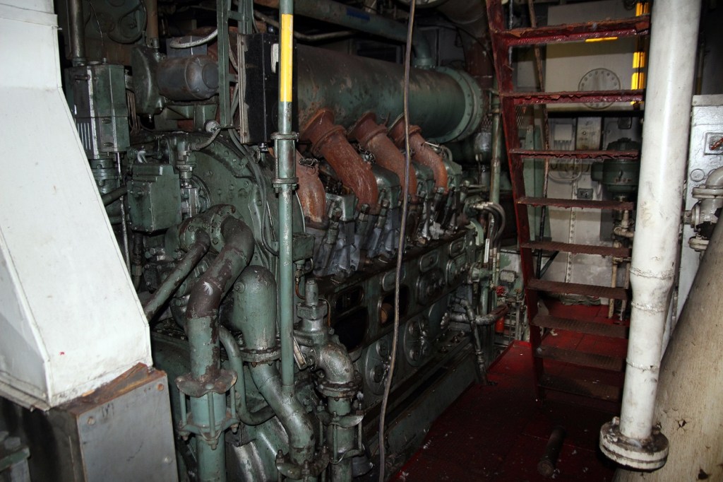
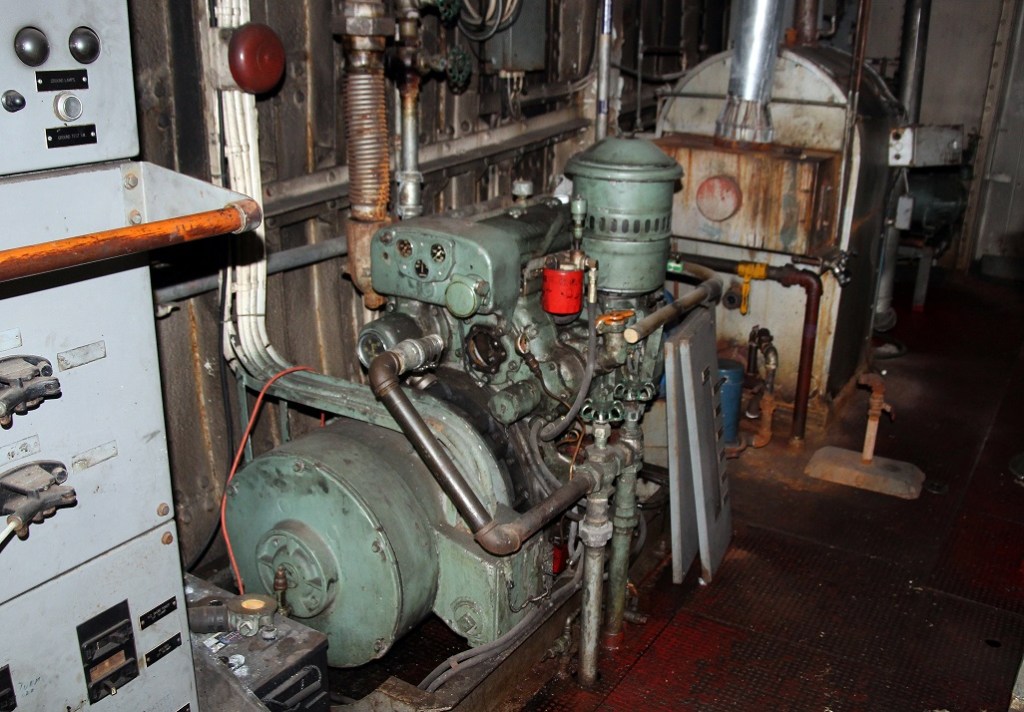
The heart of the Idaho is her Cleveland 498 engine. Note the exhaust jumpers are rusty, having no water jacket around them, and by this point, no insulation either.
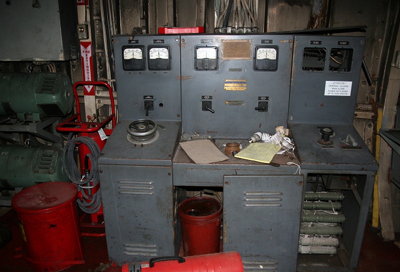
The tug had a WWII surplus, Allis-Chalmers 525V DC propulsion motor, rated for 1090kW at 720RPM. On top is a 120V DC shaft generator.
The power package installed in the Idaho. From Cleveland Diesel’s “More Power For You” brochure.
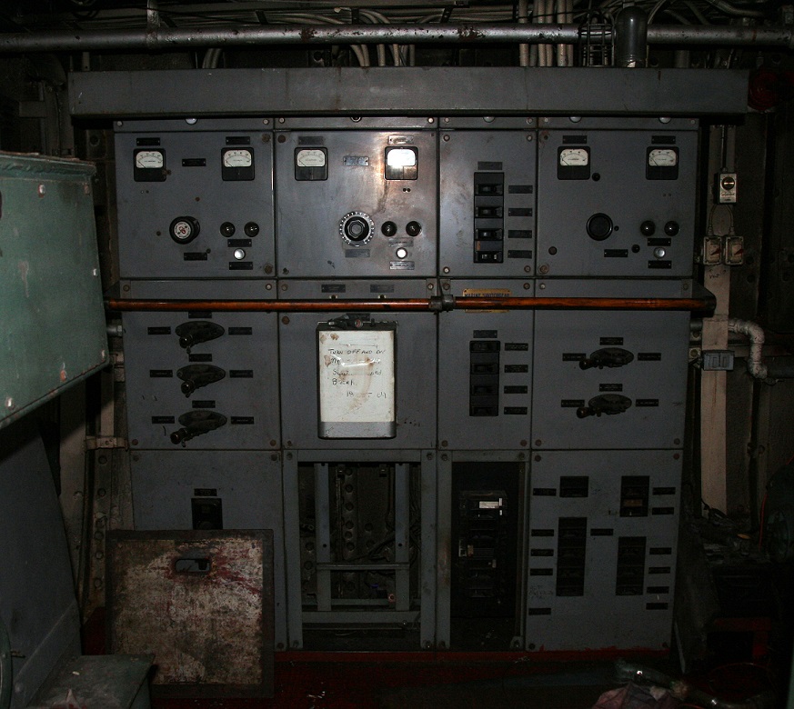
The propulsion switchboard. At left is a pair of excitation generators.
Also from the Destroyer-Escort is the propulsion motor. This was built by Westinghouse, and rated for 1225HP.
Farrel-Birmingham reduction gear, with a 4.233:1 ratio. The tug has a 102″ x 87″ stainless 3 blade propeller.
The portside, aft end of the engine room has the steering gear pump, as well as a motor-generator set. The fuel tanks are located behind the aft bulkhead.
Switchboard.
Portside of the engine, the air starter is mounted on the floor level. On top are the various gauges and governor.
Detroit Diesel 3-71 with a 30kW generator. In front is the tugs oil fired steam boiler for heating.
Air compressors.
The heart of the 498 is the De Laval turbocharger. The air intake filter is seen in the middle, with the compressor on top. A discharge tube feeds air into the intercooler on the bottom.
From the intercooler, the air fed into the roots blower (at left) from the bottom end. It was mentioned these engines sounded like helicopters.
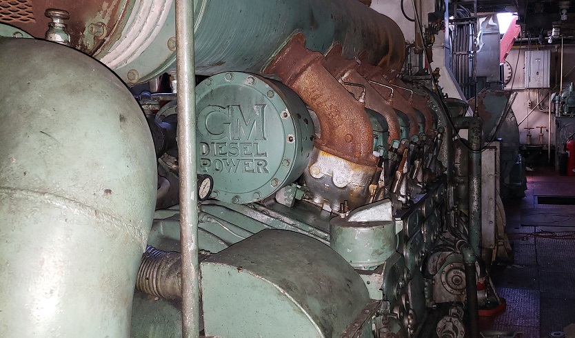
Looking aft, the large cast cover is over the camshaft balancer, proudly displaying the maker of the engine.
Taking on ode from the 248 engine, the 498 used a two piece top cover. On the bottom right is the blowdown/safety valve. Former engineers for this boat mentioned heads and head gaskets were a big failure point being addressed often.
The reason the Idaho was retired. Shortly after startup, the #4 piston locked up, thus the connecting rod snapped, in turn swinging around and slamming into the airbox and both liners.
Unfortunately, parts for the 498 were long since unavailable, and a failure like this is typically a death sentence anyway, especially in an 80+ year old hull.
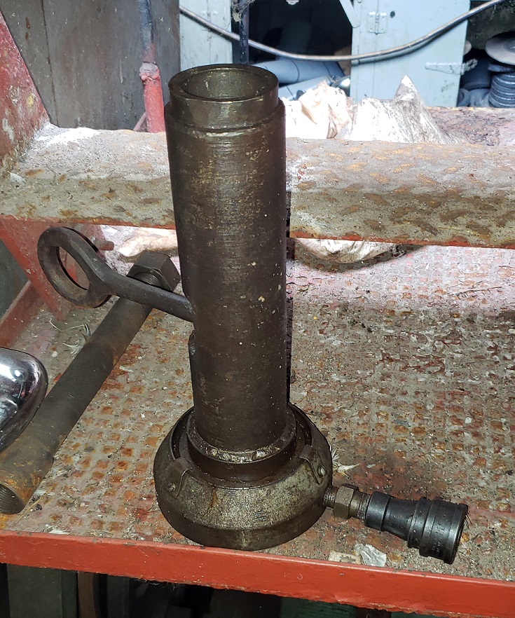
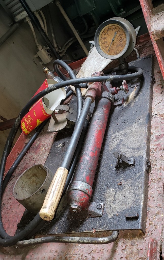
The hydraulic power pack and head tightening tool.
G tugs still have a tiller handle for rudder control, along with the Lakeshore throttle stands.
Wheelhouses were rather spartan, with a simple bench, small chart table and propulsion gauges. These tugs were only intended to do day work, with no real provisions of any kind.
These tugs were built for one purpose, docking ships, thus the low profile deckhouse. The stairs in front lead down into the forecastle.
A few basic bunks, lockers and a simple table in the bow.
The tugs official number, gouged into the steel 80+ years ago.
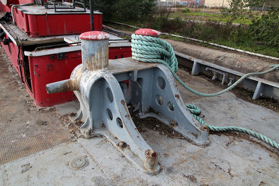
Great Lakes Towing exclusively used towing bitts manufactured by the Montague Iron Works in Northwest Michigan.
“G” tugs as they are known in the lakes, got their name from the large stack insignia.
The Idaho returning from a job in her last year in service on the Detroit River. Photo by Isaac Pennock.
Removal of the stack insignias traditionally mean the end is near. This was likely the last photo of the Idaho in one piece. Bill Kloss Photo.
Unfortunately, all things must come to an end. In January of 2019 the tug was towed back to Cleveland, and with the last few usable parts removed, the tug was scrapped. We can’t thank the Great Lakes Towing Company enough for allowing us to photo-document the tug.
With only 58 engines built, and being that virtually all of the engines stateside were replaced long ago, it is highly unlikely any of the foreign sold engines remain. We heard a rumor of one driving a water pump in Egypt, but again, this would have had to have been a relocated engine, and is highly unlikely it exists. Somebody please prove us wrong!
That wraps up our four part series on the Cleveland Diesel 498 engine. Please be sure to view the previous posts on this engine, linked on the top of this page. I will say it again, if anyone has any 498 manuals, brochures, stories, parts, anything, please get in touch with us. Should anything new arise, we will make another follow up down the road.
2022 Update – At some point this year we will post another part in this series, with some additional information we found.
Production of the Cleveland 498 commenced with the first engine shipped in May of 1956. Most production would take place in the fall of 1956 (16 engines built), and the summer of 1957 (17 engines built). 1958 saw only a pair of engines, a trio in 1959, and the last 4 were built in 1960. A total of 29 8-cylinder, 9 12-cylinder, 17 16-cylinder and 3 test engines (one 8, and two unknown) were built over the course of production, for a grand total of 58 engines.
A brochure for the engine issued not long after being announced at Powerama. Click for larger.
1) Tug Montana – Great Lakes Towing Company, Cleveland, Ohio Engine 46001, Shipped 5/2/1956, Order #1640, 8-498, 1400HP/850RPM
2) Tug Idaho – Great Lakes Towing Company, Cleveland, Ohio Engine 46001, Shipped 12/13/1956, Order #1640, 8-498, 1400HP/850RPM
Great Lakes Towing Company needs no introduction here, they are the largest tug company performing shipdocking on the Great Lakes, using “G Tugs”. We will do a more detailed feature on these down the road. Great Lakes put in the very first order for 498 engines, with the first one going into the tug Montana. Montana was built in 1929, with a single cylinder steam engine. Idaho followed a few months later. Idaho was the last “new” tug built, in 1931. Both tugs were identical and built-in house, receiving electric drive propulsion packages using surplus Destroyer-Escort generators and propulsion motors***. The Montana was retired and scrapped in 2006, and the Idaho was scrapped in 2019. The 4th and final part will be dedicated to the Idaho.
Tug Idaho shortly after being converted to Diesel power. VDD Collection.
————
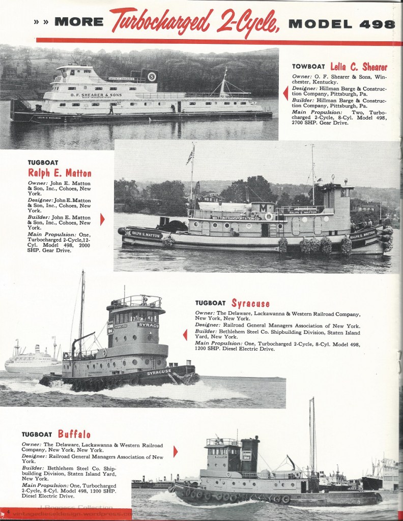
3) Tug Hoboken – Delaware Lackawanna & Western Railroad – NY, NY Engine 46003, Shipped 10/31/1956, Order #1807, 8-498, 1400HP/850RPM
4) Tug Buffalo – Delaware Lackawanna & Western Railroad – NY, NY Engine 46004, Shipped 11/30/1956, Order #1807, 8-498, 1400HP/850RPM
5) Tug Syracuse – Delaware Lackawanna & Western Railroad – NY, NY Engine 46005, Shipped 12/28/1956, Order #1807, 8-498, 1400HP/850RPM
6) Tug Utica – Delaware Lackawanna & Western Railroad – NY, NY Engine 46006, Shipped 1/14/1957, Order #1807, 8-498, 1400HP/850RPM
7) Tug Nazareth – Delaware Lackawanna & Western Railroad – NY, NY Engine 46007, Shipped 1/21/1956, Order #1807, 8-498, 1400HP/850RPM
Delaware Lackawanna & Western placed an order for 5 Diesel-Electric tugs with Bethlehem Steel of NY, built to General Managers Association (GMA) design for moving carfloats in NY Harbor. Erie Lackawanna started to sell off the tugs in the early 1970’s, these were the first to go, and every one of them was repowered not long after being sold (all being repowered by the early 1980’s). Two would go on to get GE engines, two would get Alcos, and the last an EMD. The Utica, the last survivor, is now working in Panama. These tugs will be covered extensively in my upcoming book on Railroad Tugs, coming out later this year.
Diesel Times/J. Boggess Collection
————
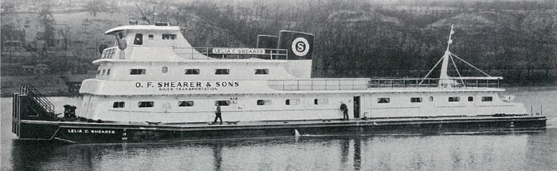
8/9) Towboat Lelia C. Shearer – O.F. Shearer & Sons, – Winchester, KY Engines 46008, 46009, Shipped 10/19/1956, Order # 1883/1884, 8-498, 1230HP/750RPM
Hillman Barge & Construction both designed and built this 2700HP diesel-clutch twin screw towboat for the O.F. Shearer & Sons company. She was repowered in 1964 with a pair of EMD 16-567C engines. The towboat kept her name through several companies and was finally scrapped in 2014. This was the first 498 powered towboat.
Diesel Times/J. Boggess Collection
————
10/11) Tug M.P. Anderson – Brown & Root, Inc. Engines 46010, 46011, Shipped 7/30/1956, 731/1956, Order # 1974, 8-498, 1400HP/850RPM
M.P. Anderson was designed by Brown & Root and built by Gulfport Shipbuilding. This 123-foot, twin screw, Diesel-Electric tug worked in the Gulf for most of her life and was also repowered with a pair of EMD 16-567C engines, with reverse-reduction gears in place of the electric drive. She is now working in Baltimore as the Austin Krause (and has one of the largest tug engine rooms I have ever been in).
The M.P. Anderson was covered in the June 1959 issue of Diesel Times. J. Boggess Collection
————
12) Tug William C. Gaynor – Great Lakes Dredge & Dock Co. Engine 46012, Shipped 9/11/1956, Order # 1956, 8-498, 1400HP/850RPM
This 94’ tug was designed by Joe Hack under Cleveland Diesel for Great Lakes Dredge & Dock. The tug was built by DeFoe shipbuilding and spent her entire life in the Great Lakes doing dredge work. Today she is working (under her original name) for Sarter Marine in Sturgeon Bay, WI. The tug was repowered with an EMD 12-567C in 1990.
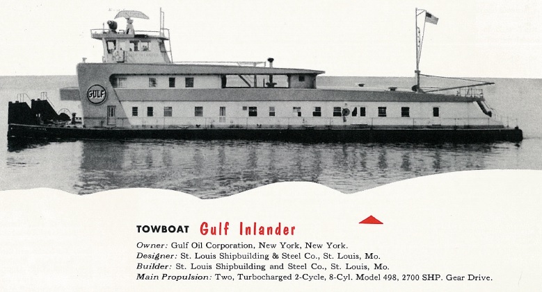
Gulf Inlander was a twin-screw towboat built by St. Louis Shipbuilding for Gulf Oil. Now known as the Mary Lynn, she was repowered and now has a pair of EMD 16-645 engines.
Diesel Times/J. Boggess Collection
————
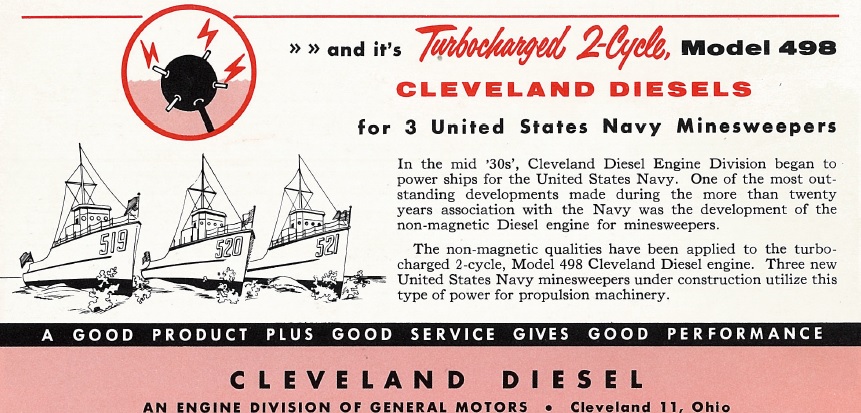
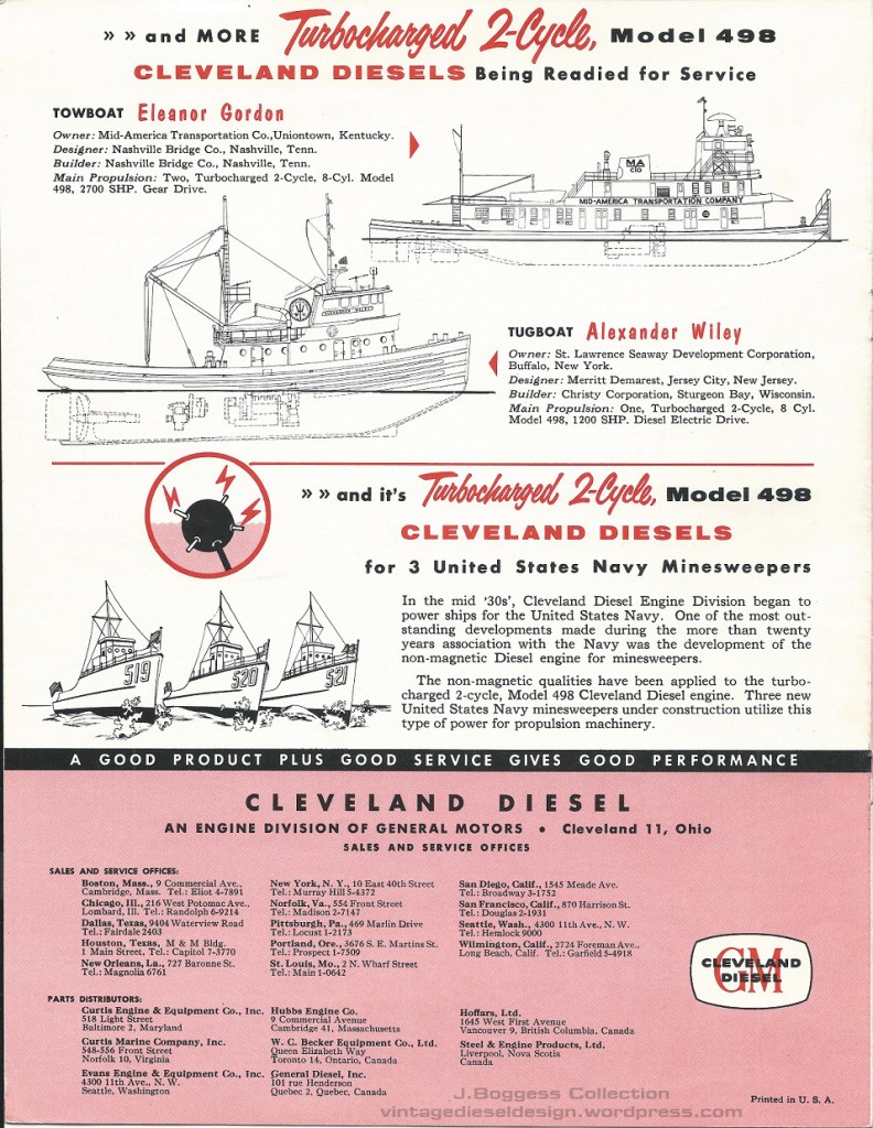
16-26) All engines 8-498 Non-Magnetic, 1400HP/850RPM
MSO-521 Assurance, Engine 46016, Shipped 10/28/1957, Order # 62562 MSO-519 Ability, Engine 46017, Shipped 7/29/1957, Order # 62562 MSO-520 Alacrity, Engine 46018, Shipped 8/5/1957, Order 62562 MSO-519 Ability, Engine 46019, Shipped 6/22/1957, Order 62563 MSO-520 Alacrity, Engine 46020, Shipped 8/7/1957, Order 62563 MSO-521 Assurance, Engine 46021, Shipped 9/10/1957, Order 62563 Naval Supply Depot (spare engine?), Engine 46022, Shipped 11/30/1960, Order 62672 MSO-519 Ability, Engine 46023, Shipped 7/31/1957, Order 62572 MSO-520 Alacrity, Engine 46024, Shipped 8/27/1957, Order 62572 MSO-521 Assurance, Engine 46025, Shipped 11/6/1957, Order 62572 Naval Supply Depot (spare engine?), Engine 46026, Shipped 11/30/1960, Order 62675
All we know about these three minesweepers with non-magnetic 498s is what we can find in Wikipedia & Navsource. We have no idea how long the 498s lasted or how well they did – it is likely the reason these ships were retired was because of the 498’s. Since these three ships were scrapped over 40 years ago, we suspect that information is lost to the ages. BUT, if there are any ex-Navy sailors out there, drop us a line.
Diesel Times/J. Boggess Collection
————
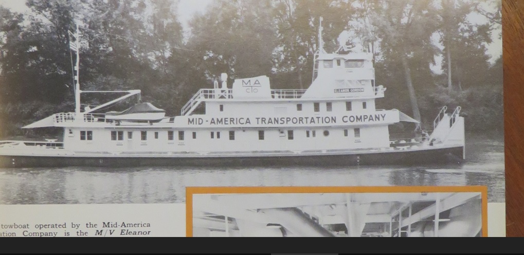
27/28) Towboat Eleanor Gordon – Two engine order, shipped 4/24/1957, Order 2039/2040, 8-948, 1400HP/850RPM.
Designed and built by Nashville Bridge Co. for Mid America Transportation Company. This 149’ towboat was powered by the pair of 498 engines with Falk reverse reduction gears. Apparently Mid-America was so displeased with these engines that the towboat was repowered within 18 months.
Diesel Times/J. Boggess Collection
The engines were sent back to Cleveland, who rebuilt them and reshipped them under a new order to Great Lakes Towing Company, who installed them into a pair of tugs, the Pennsylvania and Tennessee.
Pennsylvania would be one of the tugs assigned to work all the way down in Florida on a Navy contract in the 1990’s. Tennessee was scrapped in 2012, with the Pennsylvania being scrapped in 2019. The Pennsylvania was repowered with an EMD 12-645, however the repower was never completed before GLT decided to scrap her (?).
Tennessee was an identical sister to the Pennsylvania, and also worked in Florida. Both of these tugs were the only “G” tugs to have fixed Kort nozzles, with 102” wheels.
Tug Pennsylvania Engine 46027, Shipped 11/30/1959, Order 3936
Tug Tennessee Engine 46028, Shipped 11/30/1959, Order 3937
The Pennsylvania and Tennessee on the job in the early 1970’s. VDD Collection.
————
29) Tug Alexander Wiley Robinson Bay, St. Lawrence Seaway Development Corp. Engine 46029, Shipped 11/15/1957, Order 2573, 8-498, 1400HP/850RPM
Robinson Bay is a 103’ Diesel-Electric ice breaking tug designed by Merritt Demarest for use in the St. Laurence Seaway. The tug was repowered by Great Lakes Towing in 1991, who kept the engine as a spare parts source. The tug is now powered by a Cat 3606 with a 1750HP GE 581 propulsion motor.
The Robinson Bay at work in Northern New York. Will Van Dorp Photo.
Cypress was a 140’ towboat for the Chotin Transportation Company designed and built by J&S Shipbuilding. The towboat has been out of documentation for some time and repowering/disposition is unknown.
Diesel Times/J. Boggess Collection
————
33) Tug Ralph E. Matton, John E. Matton & Sons, Cohoes, NY Engine 51004, Shipped 7/31/1957, 12-498, Order 1726, 2100HP/850RPM
Ralph E. Matton was a New York Canal tug, designed and built by Matton. The tug was repowered with an EMD 16-567C, and later became the Mary Turecamo, and Albany. It was scrapped about 15 years ago.
Courtesy of Dave Boone
————
34) Tug Spartan, James McWilliams Blue Line, NY, NY Engine 51005, Shipped 9/14/1956, 12-498, Order 1893, 2100HP/850RPM
Spartan was a NY Canal tug, designed by Cleveland Diesel (Joe Hack) and built by Calumet Shipyard. The tug became part of the Ira Bushey & Hess family of companies and was reefed in 1986.
VDD Collection
————
35) Tug Matton #25, John E. Matton & Sons, Cohoes, NY Engine 51006, Shipped 10/20/1956, 12-498, Order 1939, 2100HP/850RPM
Matton 25 was a New York Canal tug, designed and built by Matton. The tug was repowered with an EMD 16-645, and later became the Joan Turecamo, and Everglades of Seabulk Towing. It was reefed in 2017.
————
36) Tug Matton, John E. Matton & Sons, Cohoes, NY Engine 51007, Shipped 4/29/1957, 12-498, Order 2210, 2100HP/850RPM
Matton was a New York Canal tug, designed and built by Matton. The tug was repowered and later became the Kathleen Turecamo, and Troy. It was reefed in 1990.
Courtesy of Dave Boone
————
37) Test Engine Engine 51008, Order 3133
————
38) Gen-Set, Bell Telephone Co., Philadelphia, PA Engine # 51009, Shipped 7/17/1957, Order 2118, 12-498, 1840HP/720RPM
————
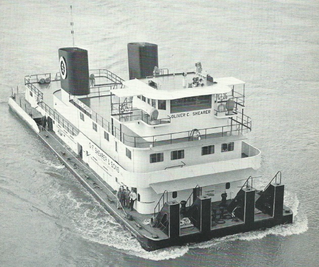
39/40) Towboat Oliver C. Shearer, O.F. Shearer & Sons, Cedar Grove, WV Engines 51010, 51011, Shipped 7/14/1960, Order 5058/5059, 7/21/1960, 12-948, 2100HP/800RPM
Shearer returned for another set of engines for a second towboat, the Oliver C. Shearer. She was designed by Friede & Goldman Inc. and built by Marietta Manufacturing. The towboat was repowered in 1965 with EMD 16-567C’s and has since been repowered several times with EMDs. The towboat is still in service under her original name.
Diesel Times/J. Boggess Collection
————
41) Development Engine Engine 57001, Order 4150, 16-498S
————
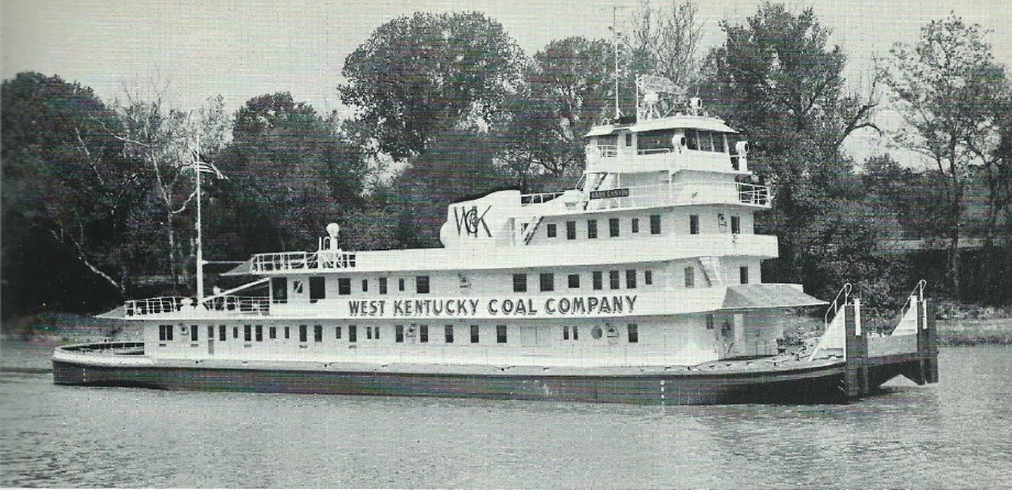
42/43) Towboat Mark Eastin, West Kentucky Coal Co., Madisonville, KY Engines 57002/57003, Order 1775/1776, Shipped 12/14/1956, 11/30/1956, 16-498, 2800HP/850RPM
The 177’ Towboat was at the time, the most powerful twin screw towboat on Inland Rivers. Repowered in 1969 with EMD 16-645 engines. In service today as the Kevin Michael.
Diesel Times/J. Boggess Collection
————
44-53) Gen-Sets, Cia Cubana de Electricidad, Havana, Cuba All engines are 16-498, 2850HP/720RPM, Order 2361
The largest order of 498 engines were these stationary 2000kW engines for a Cuban powerplant. It is unknown how long, or if they still exist. Anybody in Cuba want to go exploring for us?
Gen-Set Engine 57018, Shipped 12/28/1959, Order 3760, 16-498, 2800HP/800RPM
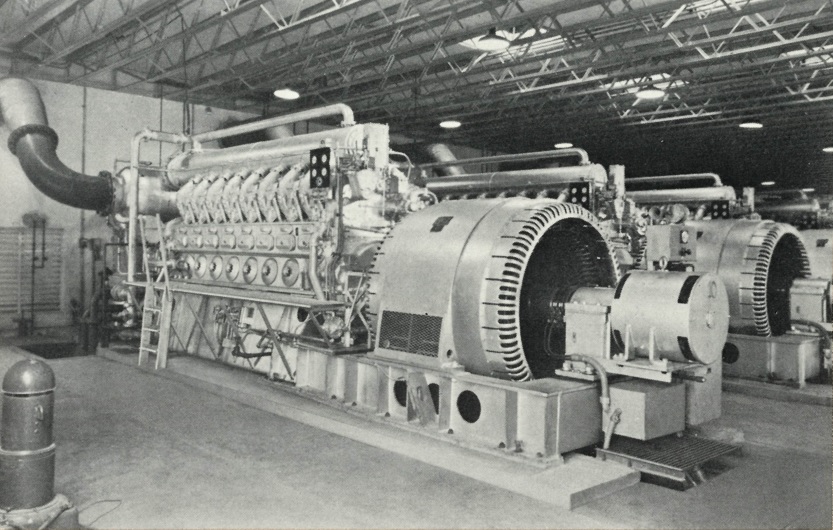
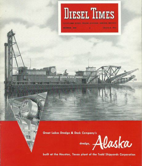
Hydraulic Dredge Alaska used a trio of 498 engines. Two engines drove the main pump drive unit, with the 3rd driving three generators, a 1250kW, 500kW and a 200kW, all on a common frame. The Alaska is still in service, but of course was repowered, and currently has EMD 710 engines.
Diesel Times/J. Boggess Collection
While most of the above users of the 498 were featured in a dedicated issue of Cleveland Diesel’s newsletter Diesel Times, the 9/1957 issue showcased the current maritime users of the engine. Click for larger.
Coming up in the final part of A Turbocharged Failure will be a post dedicated to the Great Lakes Towing tugboat Idaho, the last known 498 engine to be in use.
Thanks to my Cleveland Research Partner J. Boggess for proofing and sharing the above issues of Diesel Times.
In this second part of A Turbocharged Failure, we will go through some design features of the engine. What better way to do this then to simply go through the engine manual and show a few key areas of the engine design. Numerous additional photos of the 498 will appear in Part IV.
The initial “catalog photo” of a production 12-498, with a Falk MB series reverse-reduction gearbox.
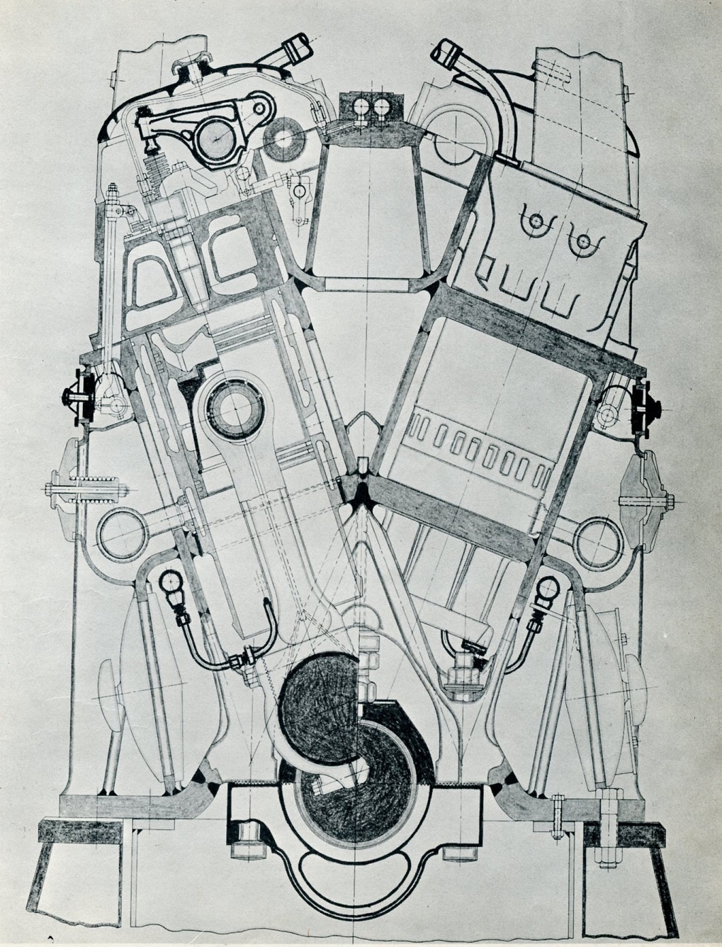
I have two versions of the 498 manual – both of which are titled as “preliminary” manuals. The older version, which is undated and likely from around 1957, and lists 4 models of the 498; a 6-, an 8-, a 12- and 16-cylinder. Like all manuals, an end view diagram is included, however this is a rather primitive, hand- drawn sketch.
Engine cross section drawings. A colorized version would never be done. Click for larger
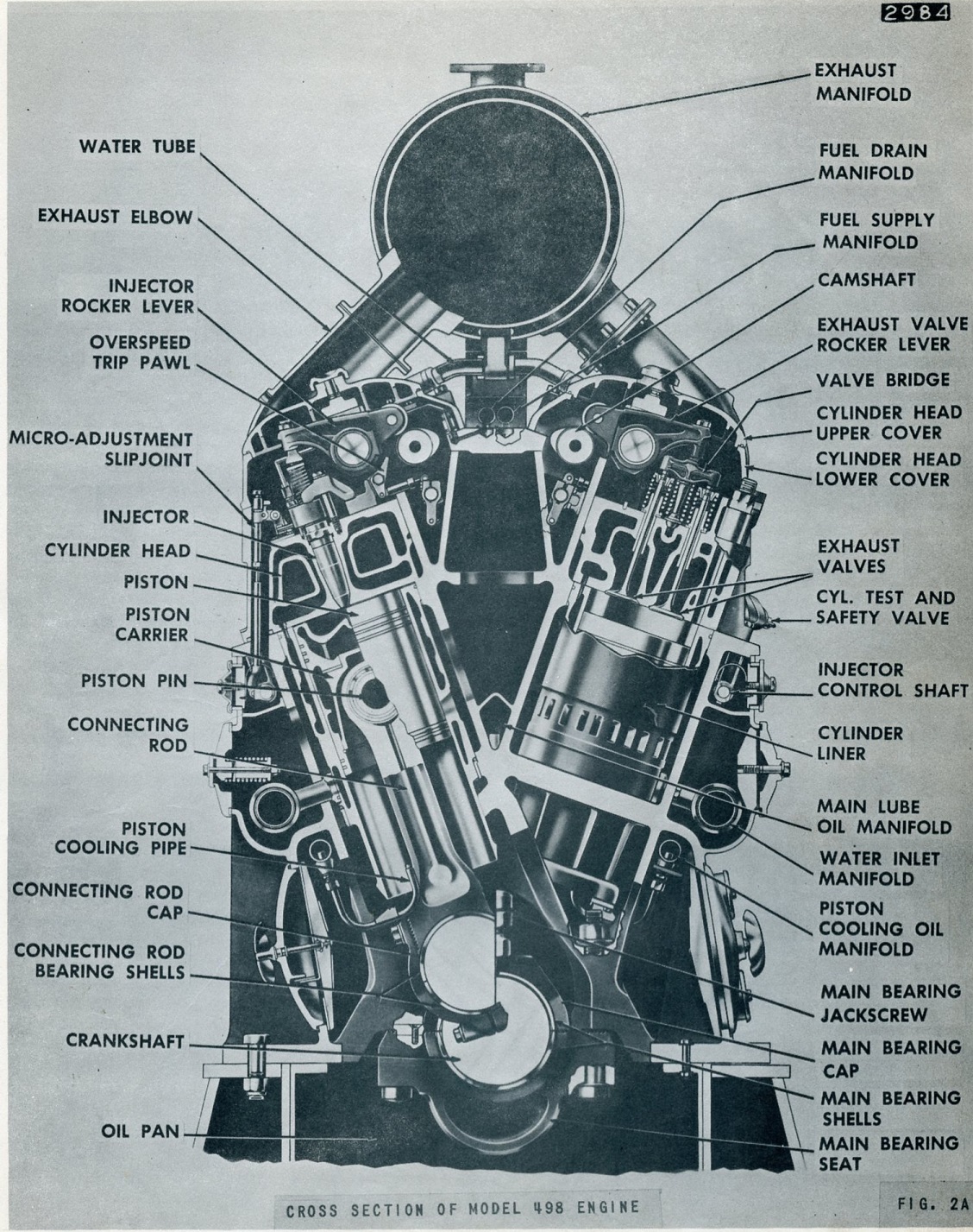
By the time the second edition was printed, dated for July of 1960, an all-new diagram was made including outlining various parts of the engine. Along with this, several additional diagrams appear in the manual, as well as some more photos of various engine parts and repair techniques. At some point the 6-cylinder version was dropped from documentation, and would ultimately never be built.
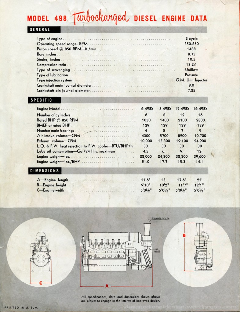
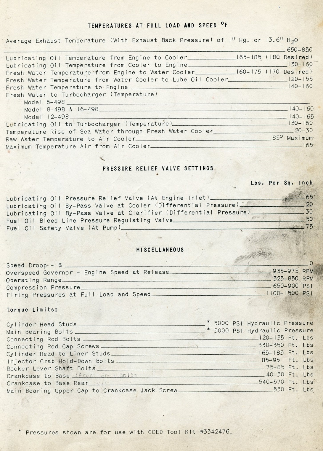
Engine data and ratings – Click for larger
Engine Operation Like all Cleveland engines, a simple lever is attached to the injector linkage. A small thumb latch allows the lever to control the engine with no governor input. When unlatched, the governor takes over all control of engine operation, used in conjunction with whatever remote propulsion control system is used. On the 498 (and some Cleveland 567’s) equipped with reverse reduction gears, a second lever was added to control the air clutch, so that propulsion speed and direction could be controlled right at the engine. 498 engines were air-started- using an air motor, unlike the 278A engines which had direct air start into the cylinders.
Engine operating levers on the 498. Click for larger
Crankcase Like the previous Cleveland models, the 498 used an all-welded crankcase of various forged parts and steel plate. A balanced, alloy steel crankshaft is used, interestingly enough the 12-cylinder crankshaft did not have any counterweights. The crankshaft is drilled for oiling the connecting rod main bearings and wrist pins. A vibration damper and balancer are mounted on the front end of the engine.
Pistons, Connecting Rods & Liners One of the biggest sets of improvements to the 498 engines from the previous 278A – are actually a few concepts borrowed from sister division EMD and the 567C engine.
While the 278A and all previous models used a semi-water deck style liner (like the EMD 567 though the “B” block) – the 498 used a sealed liner which was attached to a water manifold in the airbox by a jumper (much like the 567C).
A look in through the crankcase inspection cover at the connecting rods, showing the “pee pipe” attached to the lower end of the liner for piston cooling.
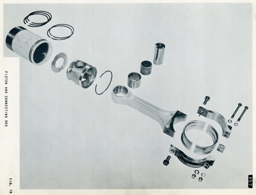
Again, borrowing from EMD, the pistons are a two-piece, trunk style floating piston (introduced on the LST 12-567 in WWII), whereas the 278A used a more traditional one-piece piston and a wrist pin. On the floating piston, the piston itself sits on a thrust washer, which in turn sits on the piston carrier attached to the connecting rod. Again, departing from the 278, Cleveland adopted the “pee pipe” piston cooling scheme EMD used since the first 567 of 1938, as opposed to the drilled connecting rod of the 278 & 268, which directed cooling oil from the crankshaft to the bottom of the piston. In the 498, the drilled connecting rod is only used for oiling the bearings and wrist pin.
Piston cooling on the 498 (top) used a drilled connecting rod to lubricate the bearings and wrist pin, however used a jet of oil which sprayed into an orifice directing oil into the cavity below the piston crown. The 278 (bottom) simply used the drilled connecting rod to lubricate everything, and used a spring check plate to retain oil in the crown.
The connecting rod of the 498 used a strap style of “cap” to contain the bearing and connect to the crankpin. Like all Cleveland’s, each connecting rod used its own bearing on the crankpin, unlike the EMD engines which use a shared crankpin and bearing set by use of the fork and blade connecting rods. This allowed the EMD to be a slightly shorter length overall, as the cylinders were directly opposite each other, versus slightly offset on the Cleveland.
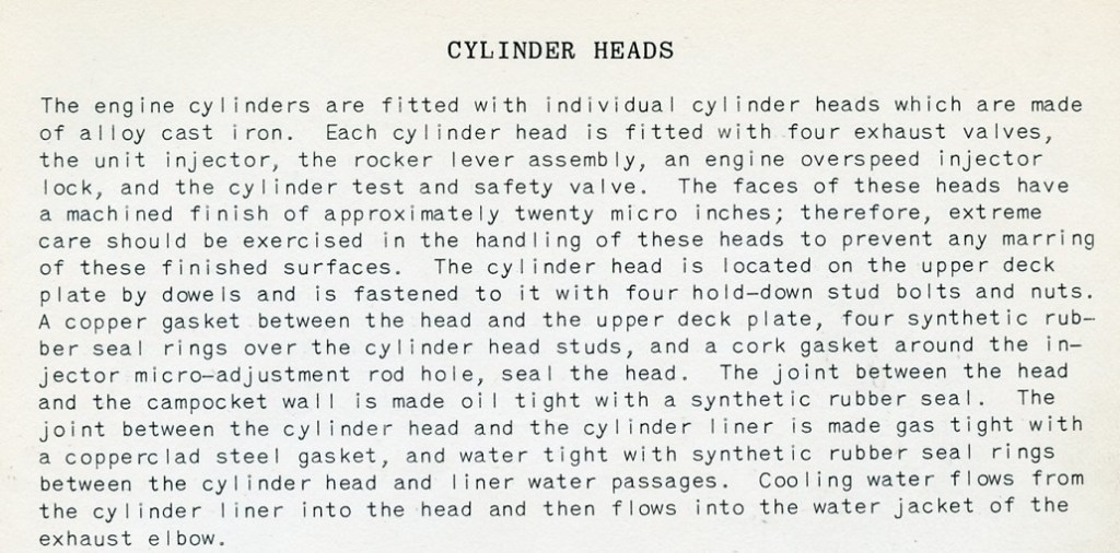
Cylinder Heads & Exhaust Again, sharing with previous Cleveland models, the 498 used individual external heads, however these had some upgrades. One of the big downfalls with the 278A style head, is there is a half-circle seal against the back of the head, which seals the cam pocket to the head. Unfortunately, this is a major source of oil leaks. The Navy devised a tool in the 1950’s to help combat this problem – a bracket clips into the injector control pocket on the block and a set screw presses the head back into the pocket, thus compressing the seal before the head is torqued down. The 498 head had a specific tab on them (visible in the above photo of the operating levers), in which a bolted clip catches, allowing one to compress the head back into the seal. The head itself was also torqued down in an interesting way. The head used stretch bolts, in which a special hydraulic tool was attached to pick up on the bolt before it was tightened down. The 498 returned to a two-piece valve cover design like the Winton 248 used. The fuel lines were also moved inside now.
Looking down on the cylinder head, which is a bit more cramped then those on the 278 family. Both fuel lines are now inside the engine, connected to main fuel lines under the exhaust manifold. The 498 used a two piece cover, like the original Winton 248 engine (I wonder if they are the same castings..). The new head design uses a combination safety and test valve, which were separate valves on the 278. EMD did not utilize these valves, which open should any excessive pressure build while the engine is running, preventing a bent connecting rod or worse. Note that the exhaust jumper has some sort of spray on insulation.
The hydraulic tool for tightening the head bolts was a rather simple process. The tension shaft is threaded onto the top portion of the stud, the tool is slipped over the tension shaft, and a nut on top secures it together. The tool is pumped up to 5,000PSI, and the actual nut holding the head down is tightened with the socket handle inside of the tool. The later 1960 manual indicates that these could also be manually torqued down to 1,030 ft. lbs. Click for larger.
A slight revision on the exhaust jumpers as well was devised. Previous engines used a completely water- jacketed jumper (the older manual incorrectly stating that the 498 had this as well), however with the 498, it was preferable to keep the exhaust gases as hot as possible entering the turbocharger – thus no water jacketing on the exhaust jumper. A small pipe exits the head and carries water to the main exhaust manifold, which was still water jacketed. The main exhaust manifold itself used diffuser sections to carry the exhaust gas to the turbocharger.
Camshaft, Accessory and Governor Drive Nothing all that special going on here. The water pumps and blower are driven off the accessory drive on the front of the engine. The camshafts are driven from the rear end of the engine by the crankshaft through a set of gears. 6- and 8-cylinder engines use one-piece camshafts, with 12- and 16-cylinder engines having two-piece camshafts. On the forward end of the camshafts, the left side has a vibration damper (not used on the 12-cylinder engine) and counterweight, with the right side having the fuel pump mounted.
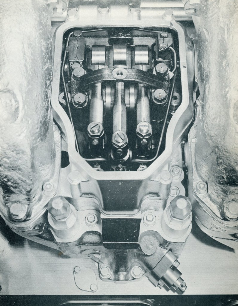
The governor drive is also driven through bevel gears on the camshaft drive. The engine uses a Marquette hydraulic governor for operation. Driven from the back of the camshaft, the overspeed governor is a bit of a complex mechanical/hydraulic device devised by Cleveland, rather than using an additional off-the-shelf Marquette governor like the previous models. When the engine overspeed’s, a centrifugal flyweight arrangement closes off oil flow to the small oil pump in the governor, forcing it to build pressure which discharges to a small piston on top. The piston acts against a spring and controls a set of linkage going to each injector rocker arm. When the overspeed is tripped, these arms engage onto the rockers, and hold the injector down in the no fuel position.
Addition 9/2021 – J. Boggess made the note that I did not catch, in that the 498 engine uses the same style of hydraulic overspeed governor that the 268A family of engine used. The 16-278A engine overspeed has a dedicated flyball thingy that when overspeed RPM is hit, it locks out all injectors until you press a reset button on the overspeed governor. The 498 and 8-268A overspeeds are self-resetting; Engine overspeeds, the overspeed governor locks out injectors until the speed gets to “normal”, then it releases the injectors, thus going up and down if the cause of the overspeed is not fixed.
Overspeed operation. Click for larger.
Oil & Cooling system The 498 uses 3 lube oil pumps, a scavenging pump and a two pressure pumps (one for main oiling, one for piston cooling). Diesel-Electric engines had an additional scavenging pump installed for the support bearings on the generators. An additional small oil strainer is mounted on the feed line for the turbocharger bearings.
The cooling system for the 498 is virtually unchanged from the 278A except for the lack of water- jacketed exhaust elbows mentioned above. The 498 uses a raw water-cooled intercooler mounted between the turbocharger and the blower.
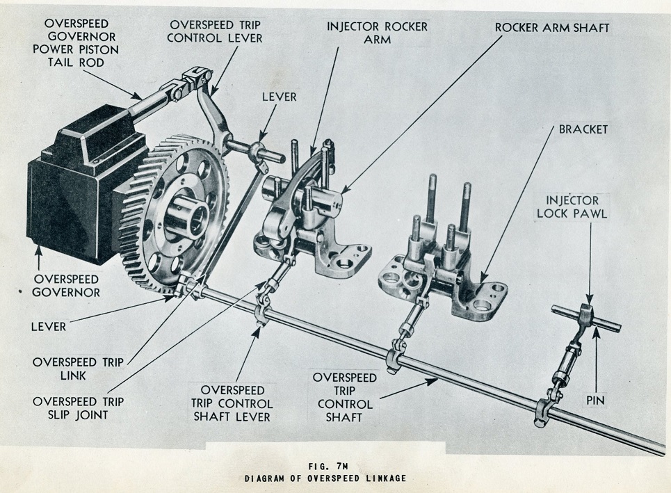
Intake & Exhaust What sets the 498 apart from her sisters is of course the use of the turbocharger. In addition to the turbocharger, the Roots blower is also used. See description below. Since the Roots blower is not doing all of the work providing scavenging air, it was found a much smaller lobe length would be required, although they did spin at a slightly higher RPM then those on the 278A.
The turbocharger for the 498 was furnished by De Laval Steam Turbine Corp. and was a basic “gas turbine driven compressor”. The Model A turbocharger was supported in its own service manual supplied by De Laval. The unit used a “monorotor” construction with both sets of blades mounted on a common central hub. The housing between the turbine and compressor is water cooled from the engine freshwater cooling system. The engine also supplies lube oil for the bearings, with an optional self-contained oil pump if so required.
The turbocharger on the 498 was mounted to the front end of the engine, with the air intake sandwiched between the turbocharger housing and the intercooler. A duct ran from the intercooler to the bottom intake side of the Roots blower.
An interesting note on the turbochargers. On most engines, the turbocharger was mounted vertically, as seen in the photo above. On the batch of engines sold to Cuba (more on this in Part III), the turbocharger was mounted horizontally. It is unknown why this was done, be it for clearance issues in the building, or some other unknown reason likely lost to history.
Another interesting note, the tug Robinson Bay (again, more on her in the next part), used an 8-498 engine. However, it appears this engine did not use a De Laval turbocharger, but it looks to be an Elliot-Bucchi design! More questions we likely will never know the reason why to.
The 16-498 engines built for Cuba used a horizontal De Laval turbocharger. The tug Robinson Bay used what looks to be a much smaller Elliot (or so it appears) style turbocharger, but the engine was still rated at 1400HP. (1959 Diesel Engine Catalog Left, 6/1958 Diesel Times Right, J. Boggess Collection). Click for larger.
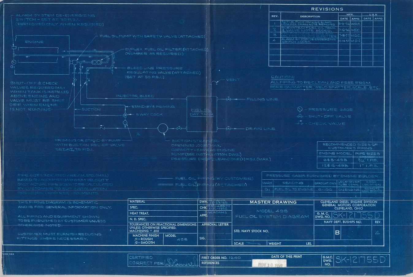
498 engine plumbing for a Diesel-Electric tugboat (click for larger)
In Part III we will go through every 498-engine built (it was only 58!)
Sidebar: My co-conspirator & former EMDer Jay Boggess & I have concluded that we really started this project about 10-15 years too late! Too many souls have moved to the Great Beyond – souls that could answer the questions our research has uncovered. We do not have clear reasons why the 498 didn’t make it (more on this in Part III and IV), only guesses and suppositions and the little bit we have been able to gather talking to guys who worked on these engines in the last few years. But then, 15 years ago, we didn’t have the internet to bring folks from across the country together, sharing common interests and information. And besides, 15 years ago, I was in junior high living 900 miles away!
Special thanks for this part go to Preston Cook, who sent me a Xeroxed scan of a 498 manual several years ago. I have since been able to acquire several versions of the original manual and service newsletters thanks to Great Lakes Towing Co., who was gracious enough to send a few surplus copies to me when we started this research project. I would love to find a service parts book, and an De Laval turbocharger manual (we only have a photo scan of it) for the Cleveland 498, and would happily pay a good price for them! My contact is in the upper Right of this page.