
In this second part of A Turbocharged Failure, we will go through some design features of the engine. What better way to do this then to simply go through the engine manual and show a few key areas of the engine design. Numerous additional photos of the 498 will appear in Part IV.
Be sure to view the other parts of this series:
A Turbocharged Failure, Part I – Engine History
A Turbocharged Failure, Part III – Uses and Installations


The initial “catalog photo” of a production 12-498, with a Falk MB series reverse-reduction gearbox.
I have two versions of the 498 manual – both of which are titled as “preliminary” manuals. The older version, which is undated and likely from around 1957, and lists 4 models of the 498; a 6-, an 8-, a 12- and 16-cylinder. Like all manuals, an end view diagram is included, however this is a rather primitive, hand- drawn sketch.
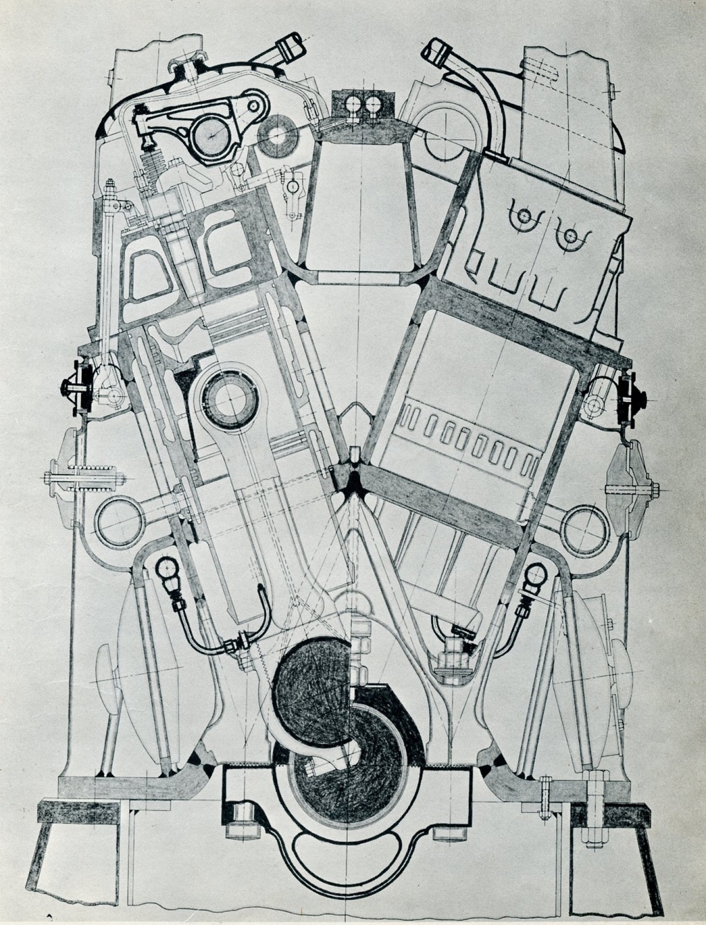
Engine cross section drawings. A colorized version would never be done. Click for larger
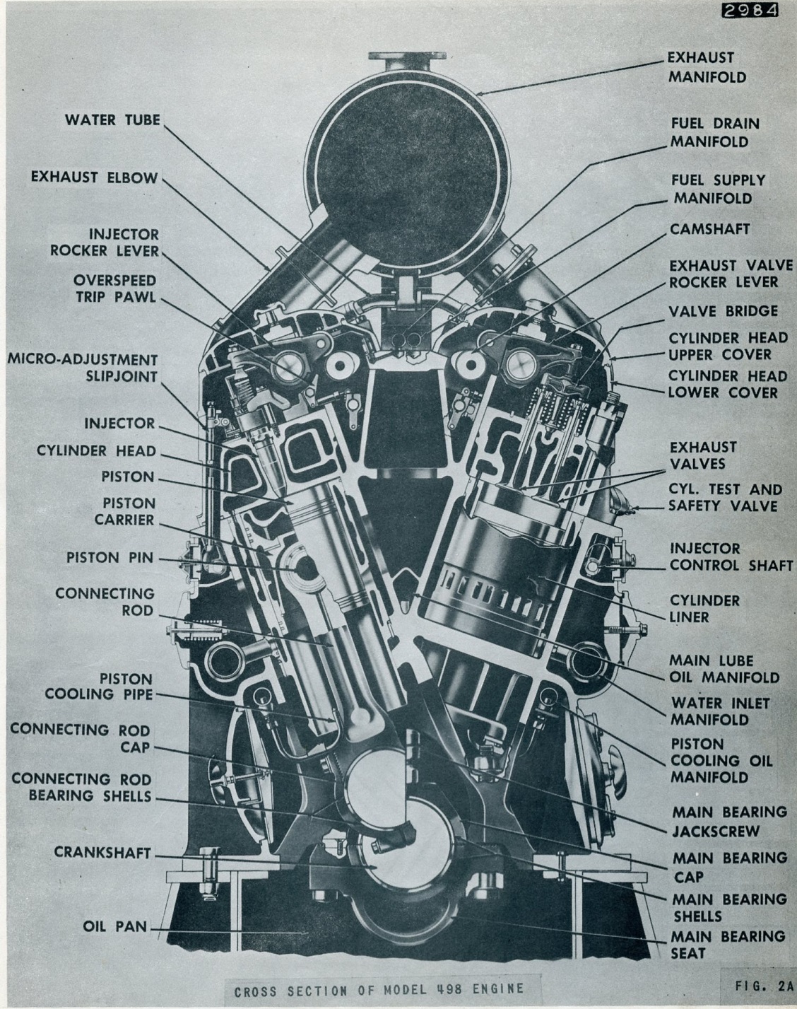
By the time the second edition was printed, dated for July of 1960, an all-new diagram was made including outlining various parts of the engine. Along with this, several additional diagrams appear in the manual, as well as some more photos of various engine parts and repair techniques. At some point the 6-cylinder version was dropped from documentation, and would ultimately never be built.

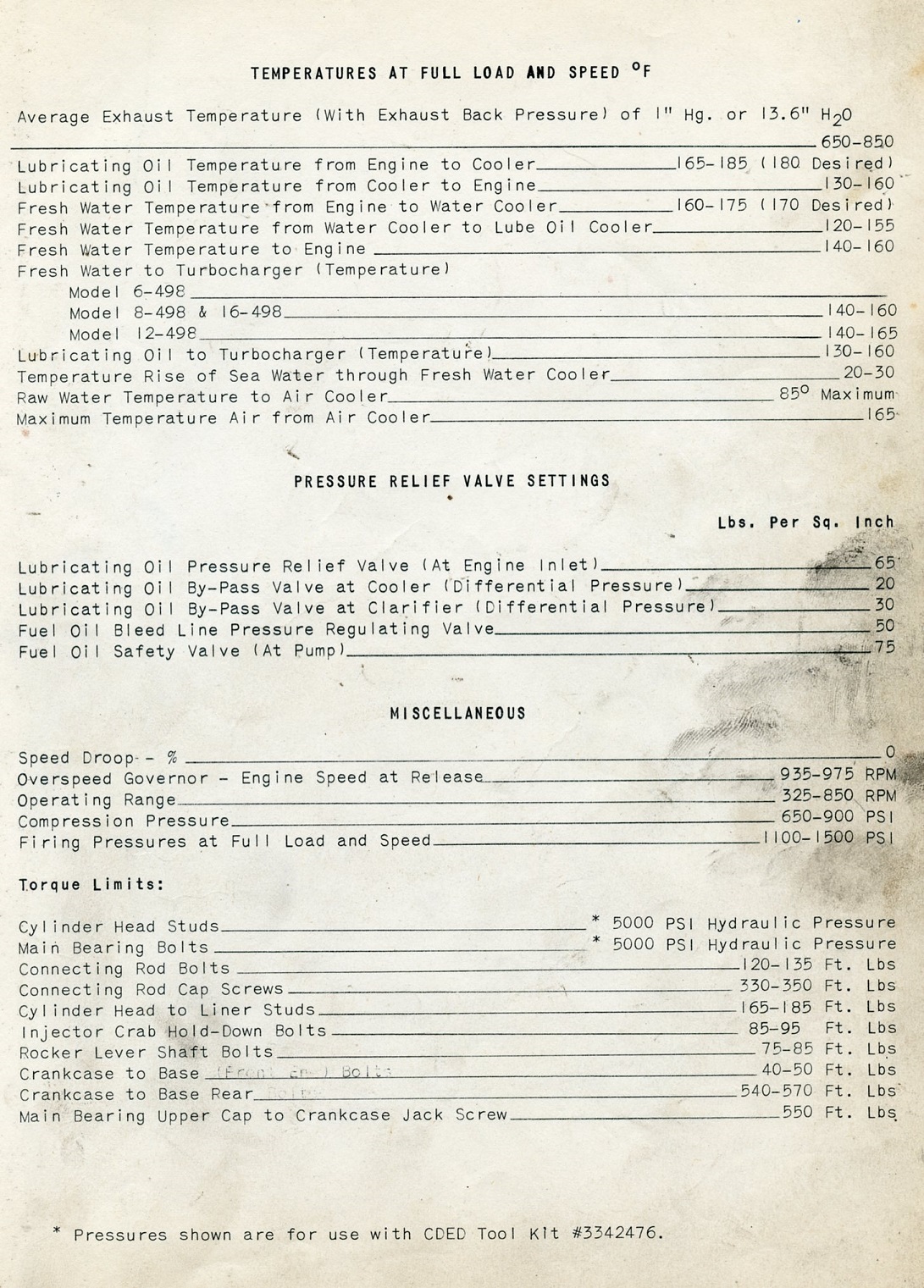


Engine data and ratings – Click for larger
Engine Operation
Like all Cleveland engines, a simple lever is attached to the injector linkage. A small thumb latch allows the lever to control the engine with no governor input. When unlatched, the governor takes over all control of engine operation, used in conjunction with whatever remote propulsion control system is used. On the 498 (and some Cleveland 567’s) equipped with reverse reduction gears, a second lever was added to control the air clutch, so that propulsion speed and direction could be controlled right at the engine. 498 engines were air-started- using an air motor, unlike the 278A engines which had direct air start into the cylinders.

Engine operating levers on the 498. Click for larger
Crankcase
Like the previous Cleveland models, the 498 used an all-welded crankcase of various forged parts and steel plate. A balanced, alloy steel crankshaft is used, interestingly enough the 12-cylinder crankshaft did not have any counterweights. The crankshaft is drilled for oiling the connecting rod main bearings and wrist pins. A vibration damper and balancer are mounted on the front end of the engine.
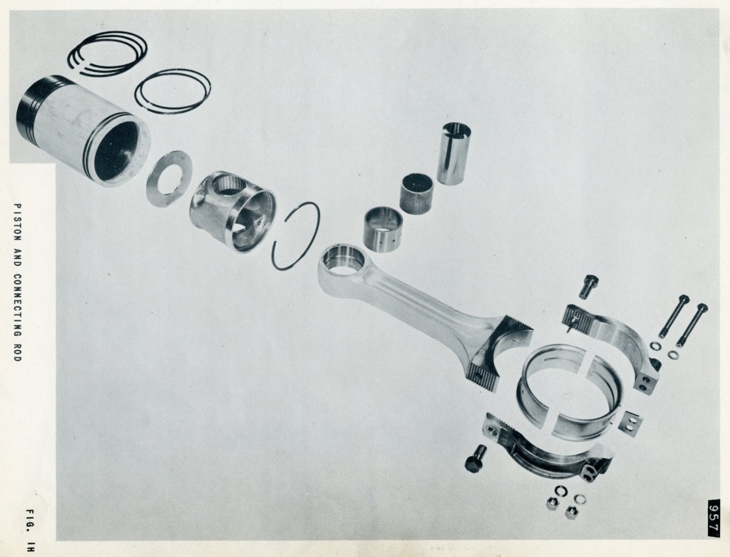
Pistons, Connecting Rods & Liners
One of the biggest sets of improvements to the 498 engines from the previous 278A – are actually a few concepts borrowed from sister division EMD and the 567C engine.
While the 278A and all previous models used a semi-water deck style liner (like the EMD 567 though the “B” block) – the 498 used a sealed liner which was attached to a water manifold in the airbox by a jumper (much like the 567C).

A look in through the crankcase inspection cover at the connecting rods, showing the “pee pipe” attached to the lower end of the liner for piston cooling.
Again, borrowing from EMD, the pistons are a two-piece, trunk style floating piston (introduced on the LST 12-567 in WWII), whereas the 278A used a more traditional one-piece piston and a wrist pin. On the floating piston, the piston itself sits on a thrust washer, which in turn sits on the piston carrier attached to the connecting rod. Again, departing from the 278, Cleveland adopted the “pee pipe” piston cooling scheme EMD used since the first 567 of 1938, as opposed to the drilled connecting rod of the 278 & 268, which directed cooling oil from the crankshaft to the bottom of the piston. In the 498, the drilled connecting rod is only used for oiling the bearings and wrist pin.


Piston cooling on the 498 (top) used a drilled connecting rod to lubricate the bearings and wrist pin, however used a jet of oil which sprayed into an orifice directing oil into the cavity below the piston crown. The 278 (bottom) simply used the drilled connecting rod to lubricate everything, and used a spring check plate to retain oil in the crown.
The connecting rod of the 498 used a strap style of “cap” to contain the bearing and connect to the crankpin. Like all Cleveland’s, each connecting rod used its own bearing on the crankpin, unlike the EMD engines which use a shared crankpin and bearing set by use of the fork and blade connecting rods. This allowed the EMD to be a slightly shorter length overall, as the cylinders were directly opposite each other, versus slightly offset on the Cleveland.
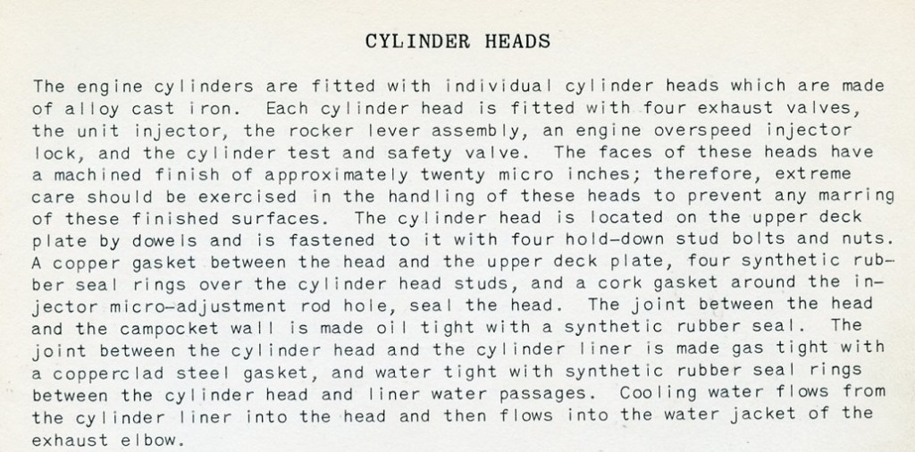
Cylinder Heads & Exhaust
Again, sharing with previous Cleveland models, the 498 used individual external heads, however these had some upgrades. One of the big downfalls with the 278A style head, is there is a half-circle seal against the back of the head, which seals the cam pocket to the head. Unfortunately, this is a major source of oil leaks. The Navy devised a tool in the 1950’s to help combat this problem – a bracket clips into the injector control pocket on the block and a set screw presses the head back into the pocket, thus compressing the seal before the head is torqued down. The 498 head had a specific tab on them (visible in the above photo of the operating levers), in which a bolted clip catches, allowing one to compress the head back into the seal. The head itself was also torqued down in an interesting way. The head used stretch bolts, in which a special hydraulic tool was attached to pick up on the bolt before it was tightened down. The 498 returned to a two-piece valve cover design like the Winton 248 used. The fuel lines were also moved inside now.
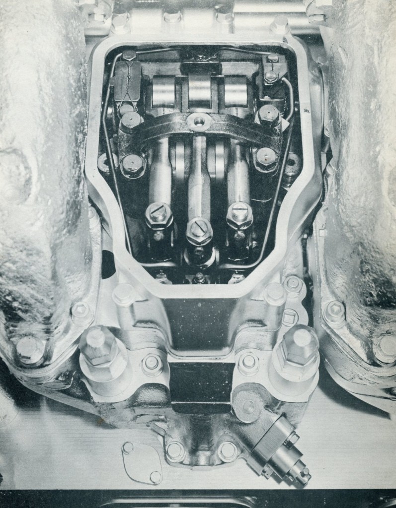
Looking down on the cylinder head, which is a bit more cramped then those on the 278 family. Both fuel lines are now inside the engine, connected to main fuel lines under the exhaust manifold. The 498 used a two piece cover, like the original Winton 248 engine (I wonder if they are the same castings..). The new head design uses a combination safety and test valve, which were separate valves on the 278. EMD did not utilize these valves, which open should any excessive pressure build while the engine is running, preventing a bent connecting rod or worse. Note that the exhaust jumper has some sort of spray on insulation.


The hydraulic tool for tightening the head bolts was a rather simple process. The tension shaft is threaded onto the top portion of the stud, the tool is slipped over the tension shaft, and a nut on top secures it together. The tool is pumped up to 5,000PSI, and the actual nut holding the head down is tightened with the socket handle inside of the tool. The later 1960 manual indicates that these could also be manually torqued down to 1,030 ft. lbs. Click for larger.
A slight revision on the exhaust jumpers as well was devised. Previous engines used a completely water- jacketed jumper (the older manual incorrectly stating that the 498 had this as well), however with the 498, it was preferable to keep the exhaust gases as hot as possible entering the turbocharger – thus no water jacketing on the exhaust jumper. A small pipe exits the head and carries water to the main exhaust manifold, which was still water jacketed. The main exhaust manifold itself used diffuser sections to carry the exhaust gas to the turbocharger.

Camshaft, Accessory and Governor Drive
Nothing all that special going on here. The water pumps and blower are driven off the accessory drive on the front of the engine. The camshafts are driven from the rear end of the engine by the crankshaft through a set of gears. 6- and 8-cylinder engines use one-piece camshafts, with 12- and 16-cylinder engines having two-piece camshafts. On the forward end of the camshafts, the left side has a vibration damper (not used on the 12-cylinder engine) and counterweight, with the right side having the fuel pump mounted.

The governor drive is also driven through bevel gears on the camshaft drive. The engine uses a Marquette hydraulic governor for operation. Driven from the back of the camshaft, the overspeed governor is a bit of a complex mechanical/hydraulic device devised by Cleveland, rather than using an additional off-the-shelf Marquette governor like the previous models. When the engine overspeed’s, a centrifugal flyweight arrangement closes off oil flow to the small oil pump in the governor, forcing it to build pressure which discharges to a small piston on top. The piston acts against a spring and controls a set of linkage going to each injector rocker arm. When the overspeed is tripped, these arms engage onto the rockers, and hold the injector down in the no fuel position.
Addition 9/2021 –
J. Boggess made the note that I did not catch, in that the 498 engine uses the same style of hydraulic overspeed governor that the 268A family of engine used. The 16-278A engine overspeed has a dedicated flyball thingy that when overspeed RPM is hit, it locks out all injectors until you press a reset button on the overspeed governor. The 498 and 8-268A overspeeds are self-resetting; Engine overspeeds, the overspeed governor locks out injectors until the speed gets to “normal”, then it releases the injectors, thus going up and down if the cause of the overspeed is not fixed.
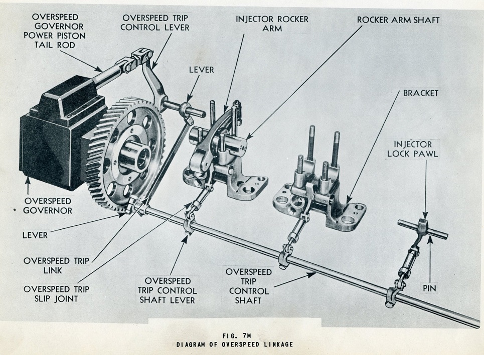

Overspeed operation. Click for larger.
Oil & Cooling system
The 498 uses 3 lube oil pumps, a scavenging pump and a two pressure pumps (one for main oiling, one for piston cooling). Diesel-Electric engines had an additional scavenging pump installed for the support bearings on the generators. An additional small oil strainer is mounted on the feed line for the turbocharger bearings.
The cooling system for the 498 is virtually unchanged from the 278A except for the lack of water- jacketed exhaust elbows mentioned above. The 498 uses a raw water-cooled intercooler mounted between the turbocharger and the blower.
Intake & Exhaust
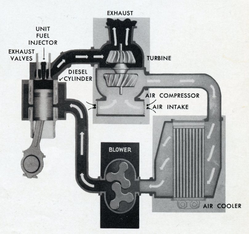
What sets the 498 apart from her sisters is of course the use of the turbocharger. In addition to the turbocharger, the Roots blower is also used. See description below. Since the Roots blower is not doing all of the work providing scavenging air, it was found a much smaller lobe length would be required, although they did spin at a slightly higher RPM then those on the 278A.

The turbocharger for the 498 was furnished by De Laval Steam Turbine Corp. and was a basic “gas turbine driven compressor”. The Model A turbocharger was supported in its own service manual supplied by De Laval. The unit used a “monorotor” construction with both sets of blades mounted on a common central hub. The housing between the turbine and compressor is water cooled from the engine freshwater cooling system. The engine also supplies lube oil for the bearings, with an optional self-contained oil pump if so required.

The turbocharger on the 498 was mounted to the front end of the engine, with the air intake sandwiched between the turbocharger housing and the intercooler. A duct ran from the intercooler to the bottom intake side of the Roots blower.

An interesting note on the turbochargers. On most engines, the turbocharger was mounted vertically, as seen in the photo above. On the batch of engines sold to Cuba (more on this in Part III), the turbocharger was mounted horizontally. It is unknown why this was done, be it for clearance issues in the building, or some other unknown reason likely lost to history.
Another interesting note, the tug Robinson Bay (again, more on her in the next part), used an 8-498 engine. However, it appears this engine did not use a De Laval turbocharger, but it looks to be an Elliot-Bucchi design! More questions we likely will never know the reason why to.


The 16-498 engines built for Cuba used a horizontal De Laval turbocharger. The tug Robinson Bay used what looks to be a much smaller Elliot (or so it appears) style turbocharger, but the engine was still rated at 1400HP. (1959 Diesel Engine Catalog Left, 6/1958 Diesel Times Right, J. Boggess Collection). Click for larger.

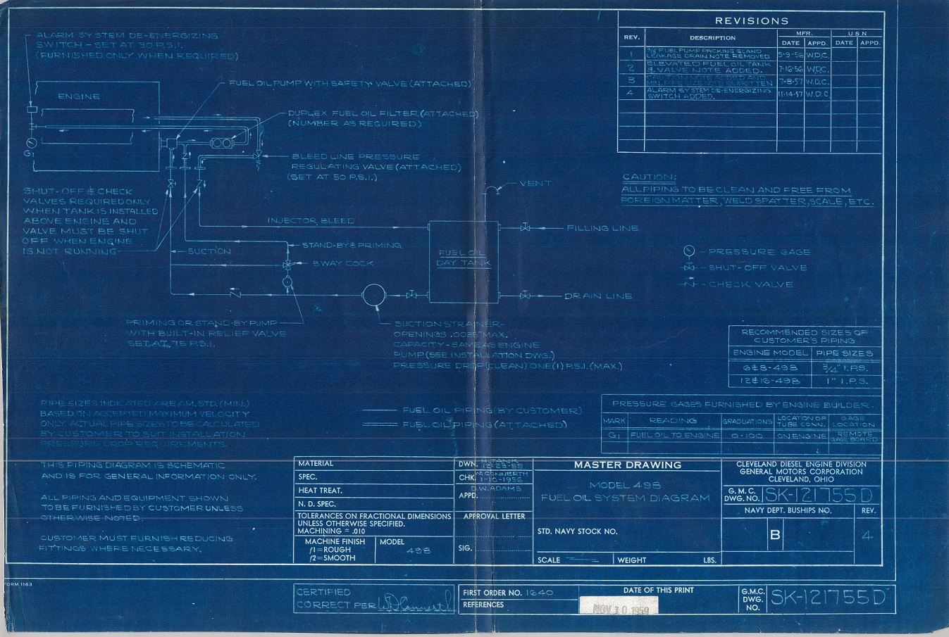
498 engine plumbing for a Diesel-Electric tugboat (click for larger)


In Part III we will go through every 498-engine built (it was only 58!)
Sidebar: My co-conspirator & former EMDer Jay Boggess & I have concluded that we really started this project about 10-15 years too late! Too many souls have moved to the Great Beyond – souls that could answer the questions our research has uncovered. We do not have clear reasons why the 498 didn’t make it (more on this in Part III and IV), only guesses and suppositions and the little bit we have been able to gather talking to guys who worked on these engines in the last few years. But then, 15 years ago, we didn’t have the internet to bring folks from across the country together, sharing common interests and information. And besides, 15 years ago, I was in junior high living 900 miles away!
Special thanks for this part go to Preston Cook, who sent me a Xeroxed scan of a 498 manual several years ago. I have since been able to acquire several versions of the original manual and service newsletters thanks to Great Lakes Towing Co., who was gracious enough to send a few surplus copies to me when we started this research project. I would love to find a service parts book, and an De Laval turbocharger manual (we only have a photo scan of it) for the Cleveland 498, and would happily pay a good price for them! My contact is in the upper Right of this page.

Worked at HK developing the Cleveland engines further for many years.
LikeLike