Delta Municipal Light & Power Part IV – Fairbanks-Morse 31A18

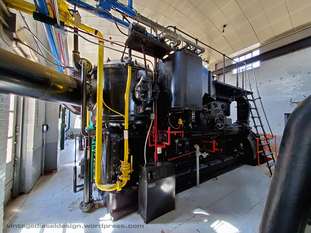
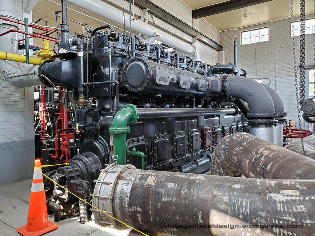
This will be our final part on the Delta plant, this week highlighting the plants largest engine, the 31A18

Part I – https://vintagedieseldesign.wordpress.com/2020/09/27/delta-municipal-light-power-part-i/
Part II – https://vintagedieseldesign.wordpress.com/2020/10/14/delta-municipal-light-power-part-ii-fairbanks-morse-33-engines/
Part III – https://vintagedieseldesign.wordpress.com/2020/11/26/delta-municipal-light-power-part-iii-fairbanks-morse-32e14-engines/

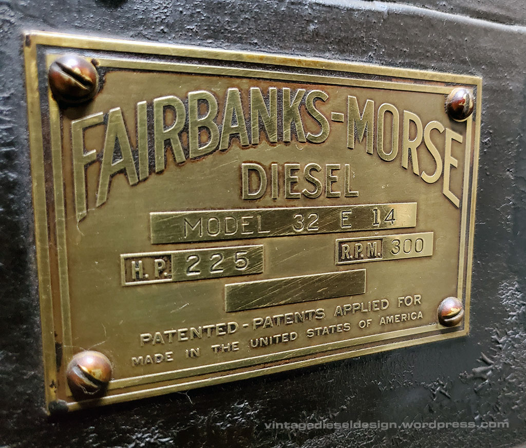
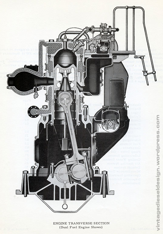
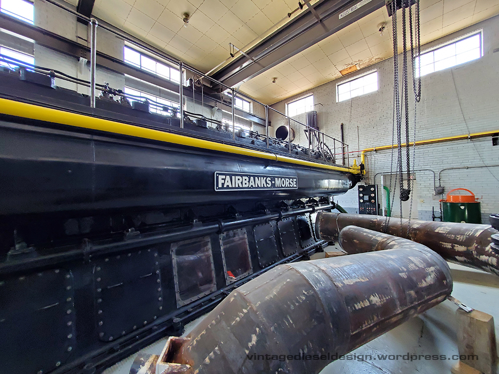
The F-M 31A18 was Fairbank’s largest production engine. In the very first post on this blog, we looked at the design of the engine: https://vintagedieseldesign.wordpress.com/2019/06/02/fairbanks-morse-31a18/

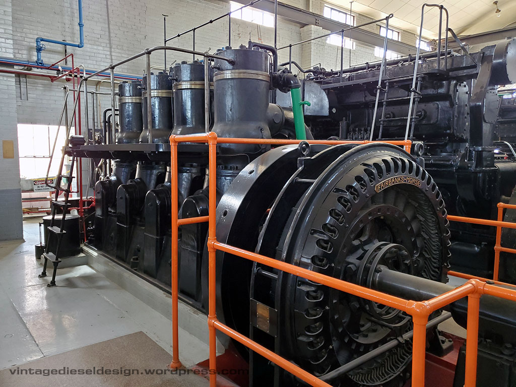
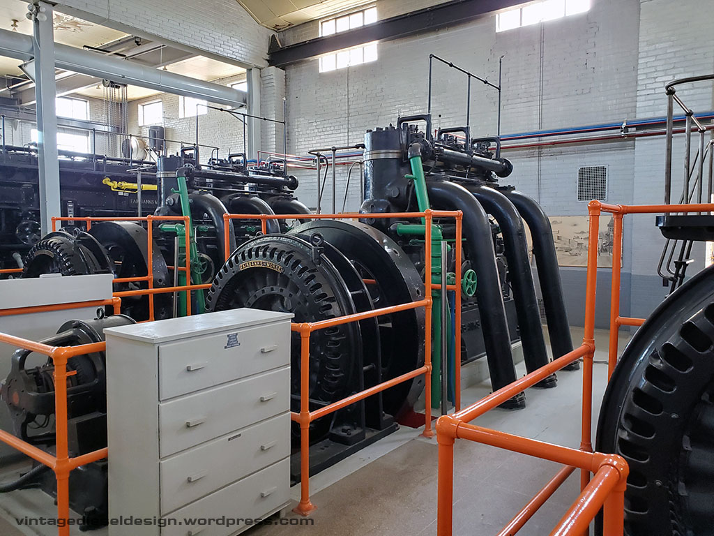
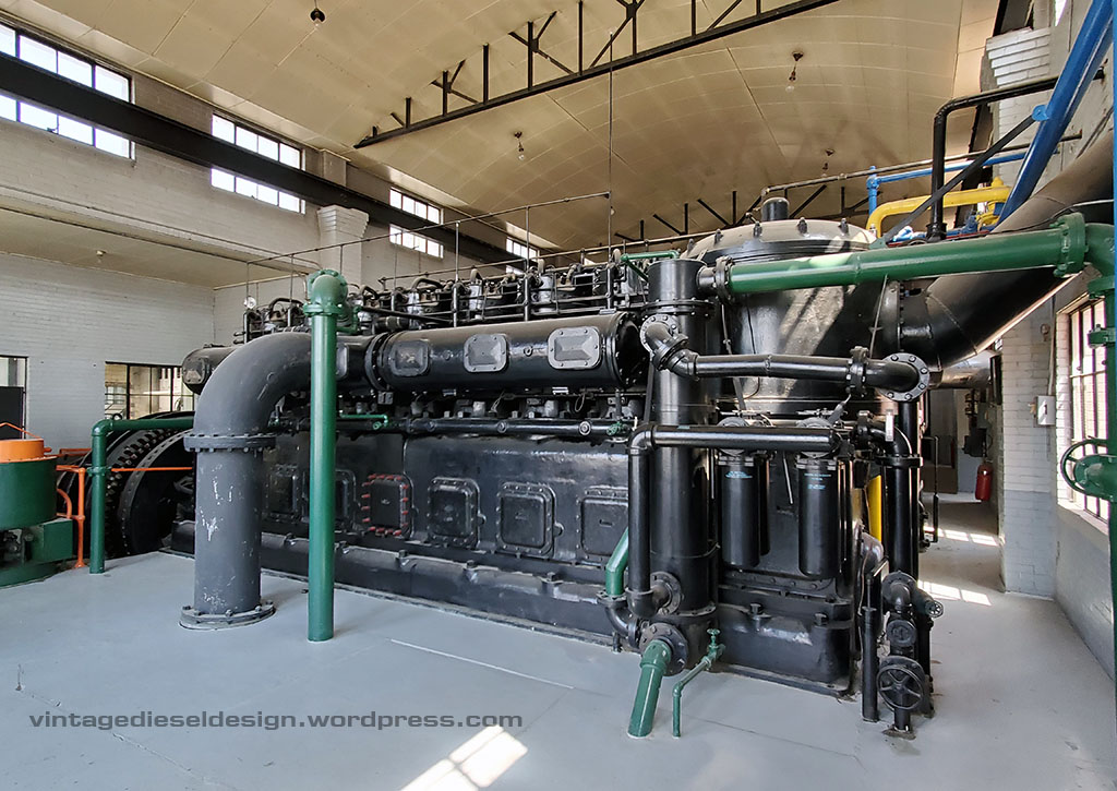
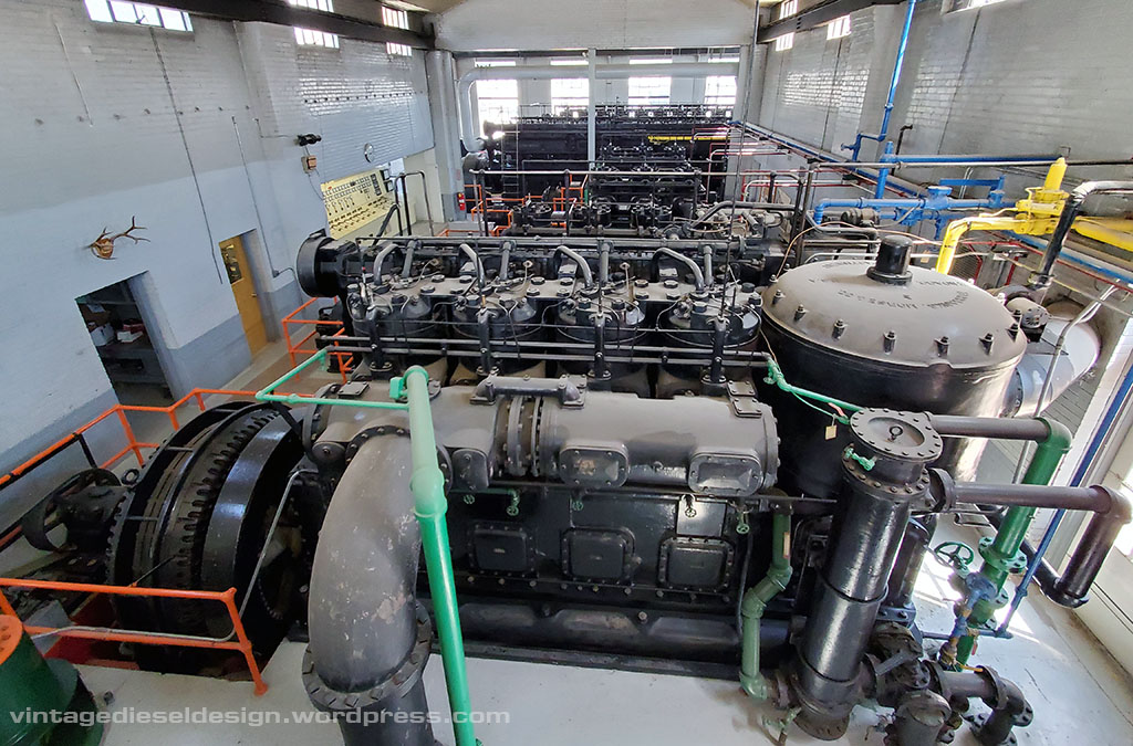
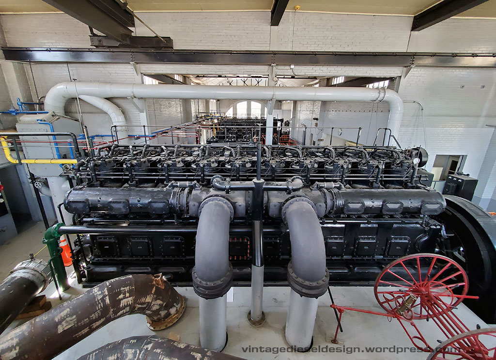
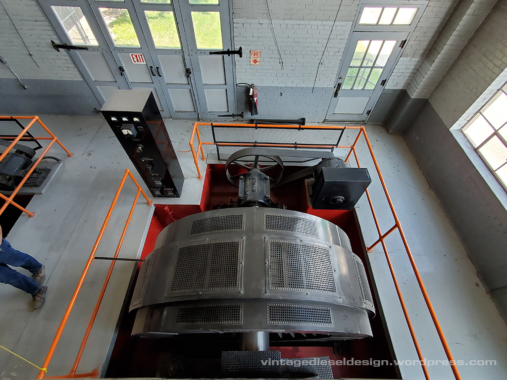
Engine #7 at Delta is a 10 cylinder, 3500HP, Dual Fuel engine. The engine is rated for only 277 RPM, and has an 18″ bore and a 27″ stroke.

Click on all of the photos for a larger version.

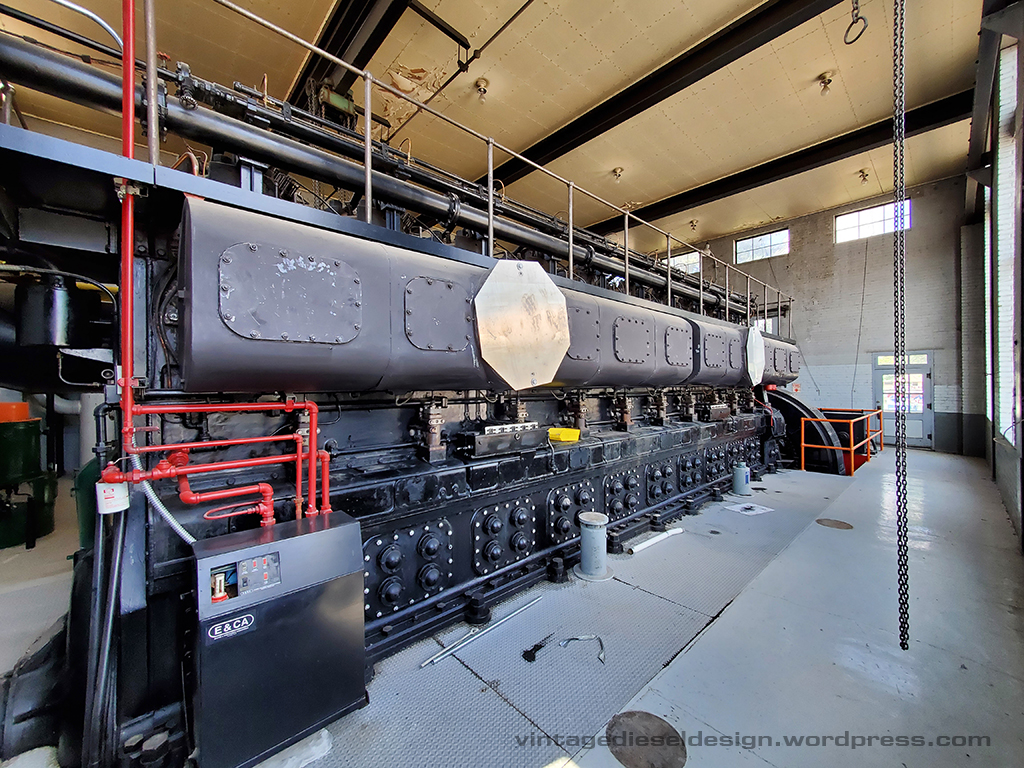
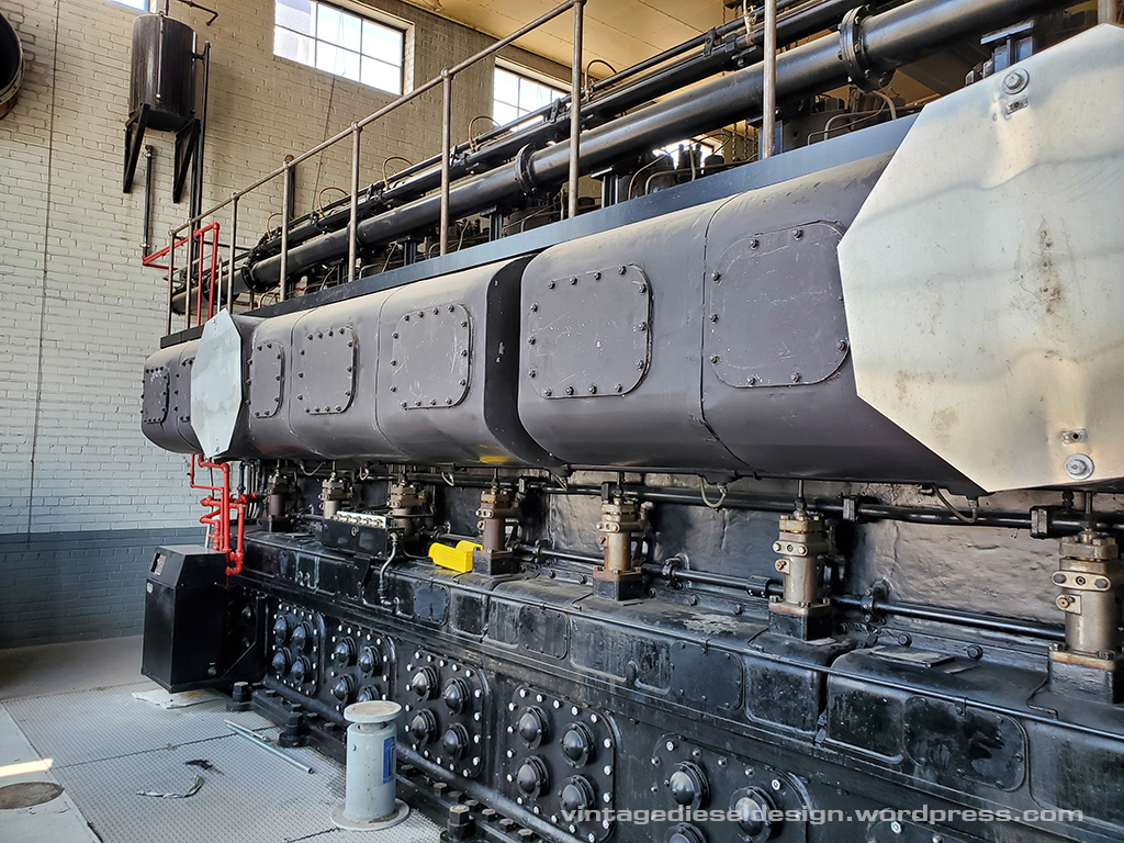
The creative use of old stop signs are covering the exhaust ports, which would turn and enter into the flood in the circular covers.

One of the fuel injection pumps. A camshaft in the box underneath drives these, with a copper line out of the top leading to the fuel injection nozzle in the head.

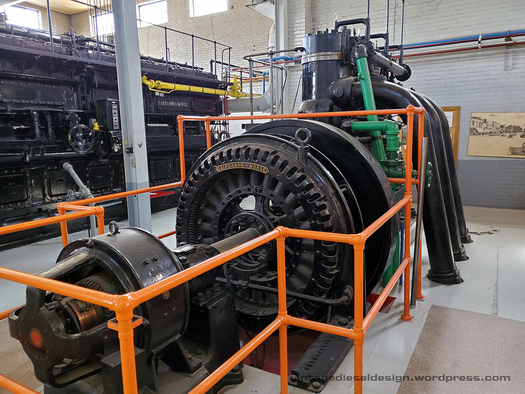
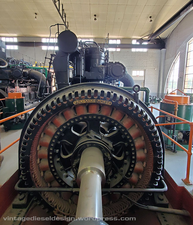
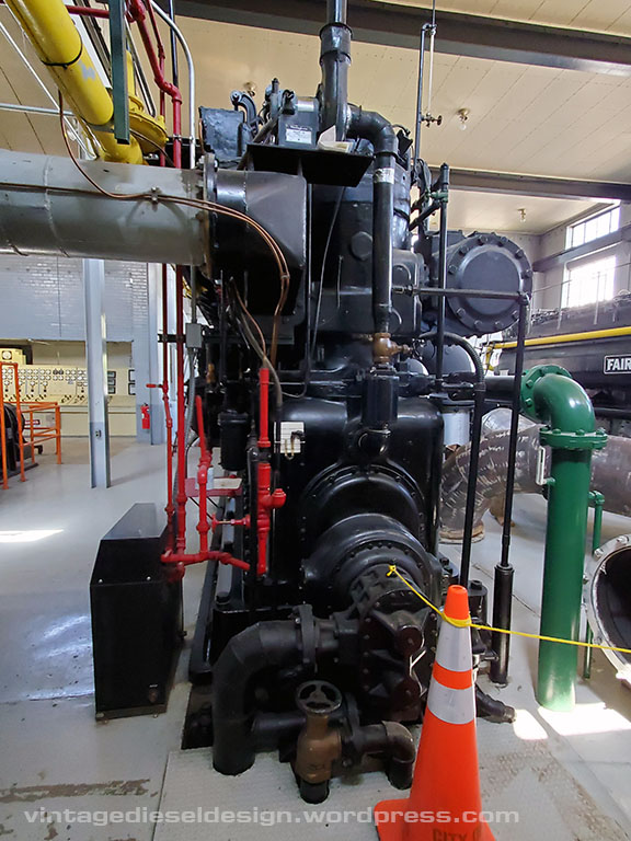
The engine drive a Fairbanks-Morse 2130kW, 2400V AC Alternator. The excitation generator is belt driven off off the end.

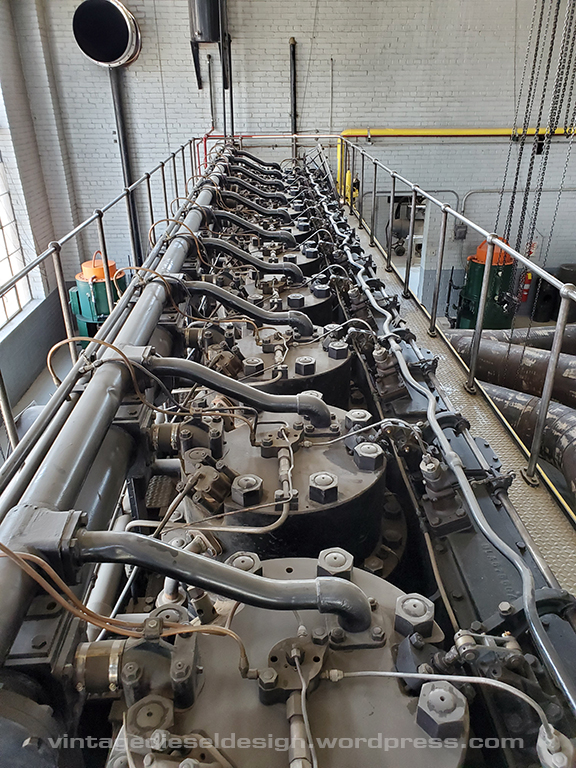
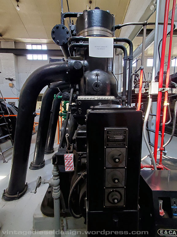
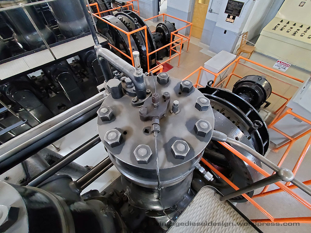
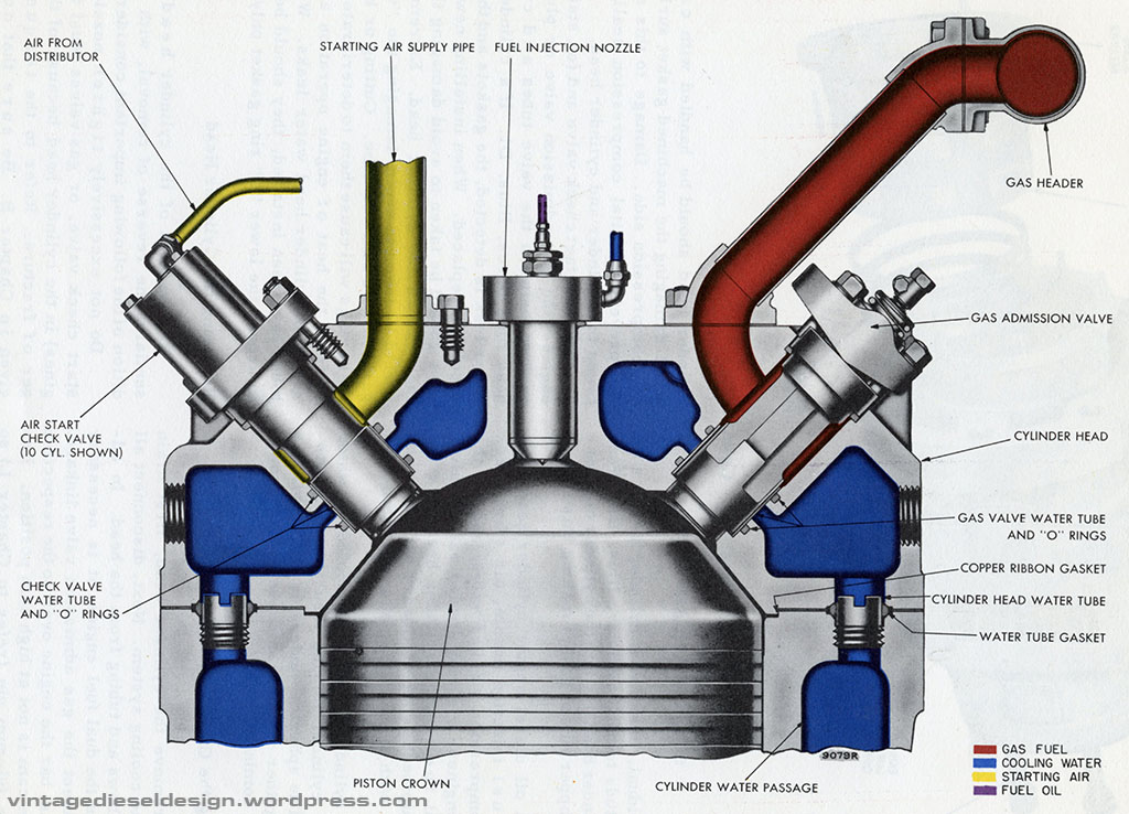
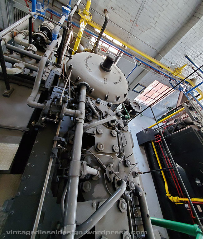
Looking down at the top of the cylinder head. The large pipe leading into the top of the head is the incoming Natural Gas supply. Going clockwise, is the gas admission valve driven from the upper camshaft, the air start check valve, with the air supply under it, jacket water exit into the upper water header, above that is the cylinder relief valve. In the center is the fuel injection nozzle. According to the builders plate, this engine is a 31A18 – FM documentation calls the Dual Fuel engine a 31AD18, maybe this engine was converted after installation?

The pipes in the foreground are the previously mentioned exhaust pipes, which were removed for remediation.

Just outside of the engine hall, is a small clean air room. Inside, is the scavenging air blower for the engine (all 10 cylinder engines used an external blower) – a Roots-Connersville 24″ centrifugal blower. The blower, is rated at a whopping 300HP and moves 17,500CFM of air.

Be sure to read our post on Roots Blowers from a few weeks ago: https://vintagedieseldesign.wordpress.com/2020/10/03/who-is-roots-and-why-does-he-have-a-blower-named-after-him/

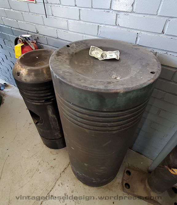
Just how big is an 18″ piston? Here it is with a dollar bill for reference..

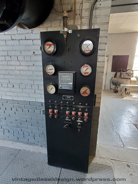
Gauge and alarm panel – Just not as cool as those 1930’s era ones on the 32E engines..

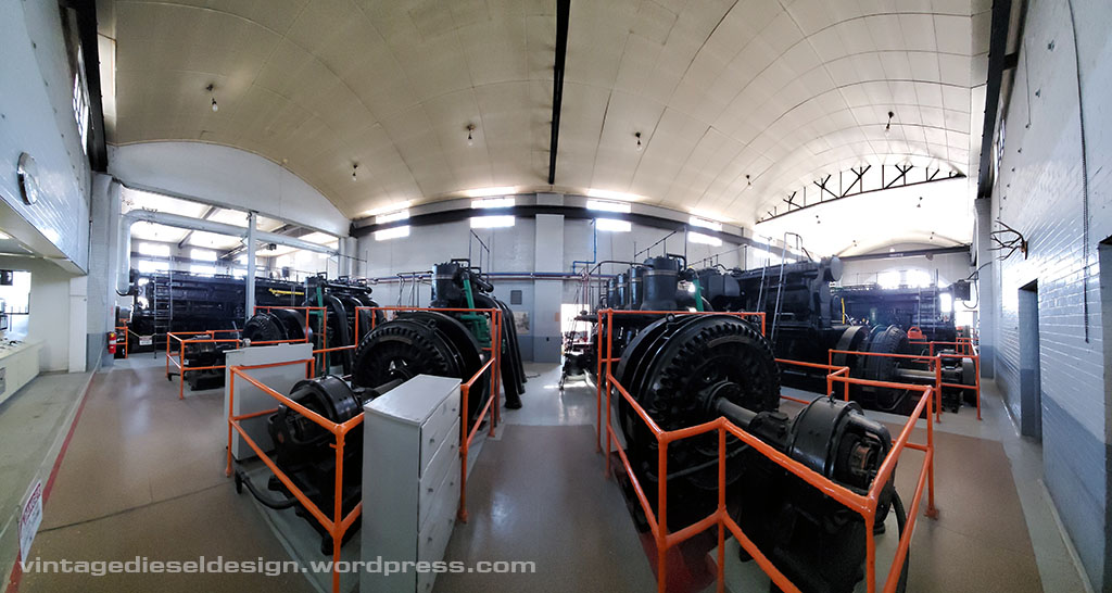
The photos here simply do not do this engine justice, and just how BIG it is!

Lubrication chart for the engine. I would LOVE to add one of these to my collection. Anyone got one they want to sell?

This concludes our tour of the Delta Municipal Light & Power Plant. Thanks again to the guys for the fantastic tour! I can only hope that this plant can be saved, or at least some of the engines. I would love to see the 31A18 saved, but realize that would be one hell of a feat, due to the shear size. That little 4 cylinder 33 would be a neat museum piece as well.. I may make another post down the road with some other random photos in the plant I took.

Next week starts a new series – Historic Boat Profiles, with our first featured boat being the tug M. Moran, Moran Towing’s first twin screw tug.

Delta Municipal Light & Power Part III – Fairbanks-Morse 32E14 Engines

I am way behind in posts as usual, so here we are continuing with the Delta series, this week highlighting the 32E engines, the original engines at the plant.

Part Ihttps://vintagedieseldesign.wordpress.com/2020/09/27/delta-municipal-light-power-part-i/
Part IIhttps://vintagedieseldesign.wordpress.com/2020/10/14/delta-municipal-light-power-part-ii-fairbanks-morse-33-engines/

Moving down the line of engines we get to engines #3, 4 and 5, all of which are Fairbanks-Morse 32E14 engines. The 32E was a descendent of the model Y engine, first introduced in 1923, and subsequently went through several upgrades over the years. The engine, offered in two sizes: A 12″x15″ and a 14″x17″. The engines were identical, other then the bore and stroke, with the 12″ offered in 1, 2 and 3 cylinder models, and the larger 14″ in 1, 2, 3, 4, 5 and 6 cylinder options. The 32E engine is a 2 stroke Diesel, and used a unique backflow scavenging, in which on the up stroke of the piston, air is pulled into the crankcase through a simple air valve on the crankcase door, is compressed on the downstroke, and when the piston uncovers the exhaust and intake ports on the liner, the compressed air forces the exhaust out, a very simple and effective method, requiring no camshaft operated valves in the cylinder head. An oil pump kept a force feed lubricator full, which handled the oiling on the cylinder walls, wrist pins and crank pins, as well as keeping a certain oil level maintained at each of the main bearings using a series of drilled passageways. The engine had no water pump of its own, relying on an external pump in the plant. A plunger type fuel pump was operated by a camshaft on the governor drive. The engines originally used a very basic FM flyweight style governor, and later used a Woodward IC unit. The 32 line would become one of the most popular engines of its time, powering numerous rural communities and small business (be it power generation or through a line shaft).

Click on all photos below for a larger version.

Engine #4 is a 300HP engine at only 300RPM, driving a 148kW alternator.

The 32E engine commonly used a very basic exhaust system, where each cylinder simple exhaust into a downward pipe, that tie into a chamber under the floor that runs outside to the muffler.

Engines #4 and 5 are smaller 3 cylinder, 225HP engines. Unfortunately, I did not get the size of the alternators that they drive.

The pipe above the exhaust manifolds is the upper water header. These are extremely basic engines, and while today are tiny in terms of ratings, several are still in service all around the country, not only in their original plants, but many preserved at old engine clubs.

Looking down on the cylinder head, we see the fuel injection nozzle in the center, as well as the jacket water exit.

Behind each alternator, the same shaft also turns the excitation generator.

Next week will be the final part of the Delta series, covering the biggest engine in the plant, the 31A18. After that we will start a new series, Historic Boat Profiles, as well as returning to vintage advertising and some great articles which have been in the works for several months behind the scenes.

I hope everyone had a great Thanksgiving!

Delta Municipal Light & Power Part II – Fairbanks-Morse 33 Engines

Continuing from Part I – https://vintagedieseldesign.wordpress.com/2020/09/27/delta-municipal-light-power-part-i/

The Delta plant is home to a trio of F-M model 33 engines. Before we get to those, here is a little background on the Model 33 engine.

The Model 33 engine was the next model in line after the 32 series, and was introduced around 1930. The engine was ultimately offered in 3 bore sizes – a 12″, 14″ and 16″. The engine was FM’s first pump scavenged engine, moving up from the older crankcase scavenged 32. Like the predecessor, these were rather simple engines. No intake or exhaust valves, mechanical fuel injection (in a time when air injection was still somewhat common) and a split lubrication system using both an engine driven pressure pump and a force feed mechanical lubricator.

In the case of this post, we will be describing the 16″ bore model, which has a 20″ stroke rated at 300RPM. FM offered these engines in 4, 5, 6, 7, 8 and 10 cylinder sizes. The engine was available with a dual fuel option, meaning it could run on Diesel, or Natural Gas with Diesel acting as a pilot fuel. A second upper camshaft drives a series of gas valves at each cylinder head. The Delta plant has 3 of these engines:

#1 – 8 Cylinder 33F16, Dual Fuel engine. 16″ bore and 20″ stroke, 1400HP
#2 – 4 Cylinder 33D16 Dual Fuel engine. 16″ bore and 20″ stroke, 700HP
#6 – 10 Cylinder 33F16 Dual Fuel engine, 16″ bore and 20″ stroke, 2000HP

Unfortunately I did not ask as to the chronological history as to just when these engines were installed.

Lets start at Engine #1Click on images for larger versions

Looking at #1, we see the main exhaust leading into the floor, where it then heads outside into the muffler. Mounted on the side of the scavenging pump is the lube oil heat exchanger, as well as a set of oil strainers.
On the side of the engine is the starting hand wheel, fuel injection pumps, and the Woodward governor.
On the left side is the Natural Gas header pipe, with the starting air pipe being the other large pipe going into the head. In the center is the fuel injection nozzle.
A look at the cylinder head cross section.
Top of the scavenging pump.
Control side of the engine. I honestly do not know what the additional box is between the scavenging pump and the intake belt is, but I do believe it is an intercooler of sort. I have not seen this on any other FM engine, and I did not notice it to ask when I was there. I imagine it has to do with emissions.
The engine drives an 835kW AC Alternator. F-M supplied all of the electrical gear to the plant as well.
Straight on side view of the engine. This engine in marine form was known as the model 37F16, a direct reversible engine common to tugboats in the 1950’s.
A final look at Engine #1.

Engine #2

Engine #2 is a small, 4 cylinder 33D16 engine. F-M would upgrade the letter designation as the engines advanced through the years, thus this is the older of the trio, being a “D” engine.

Other then being short 2 cylinders, the engine is exactly the same as #1 above.
What is interesting is the additional plates between the cylinder heads. I have never seen these on a marine engine.
While I thought I thought I got photos of everything, I missed getting a photo of several data plates, thus I do not know how large the Alternator is that this engine drives.

Engine # 6

Engine #6 at Delta is the 2nd largest engine of the plant, rated at 2,000HP.

Notice anything missing? No scavenging pump! The 10 cylinder model utilized a motor driven centrifugal blower, mounted externally. We will discuss these more when we get to the 31A18.
On the front of the engine is the main lube oil pump.
Again, standard controls like the previous engines. Note that this one is the opposite rotation though.
The gauge board. Note the feed lines coming up from the floor.
The exhaust side of the engine. Note the large grey pipe in the background – this is the scavenging air intake.
This engine drives a 1200kW alternator, at 60 cycles.

In the next part we will go over the trio of 32E14 engines at the plant.