A few weeks ago at work, we changed out a power assembly on one of our locomotives. I took the Go-Pro with me and set it up on time lapse to get some footage.
We only changed out a short pack – the head, liner and piston. The original carrier and connecting rod stayed. Check out the above video, it takes you thought almost the whole process other then setting the valves and injector at the end. Thanks to my friend Chris for putting my footage together into something presentable! Be sure to check out his YouTube page for some great midwestern railroading videos – https://www.youtube.com/@christhompson3786
3rd in our series of Historic Boat Profiles – Links to the others will be on the bottom of this posting.
New York City is home to one of the most recognizable towing companies in the world – Moran Towing & Transportation. Moran was founded back in 1860 by Michael Moran. The company would become one of the largest tugboat firms on the east coast. But, this is not a history of Moran Towing – for that I defect to the company history on Tugboatinformation: https://tugboatinformation.com/company.cfm?id=59
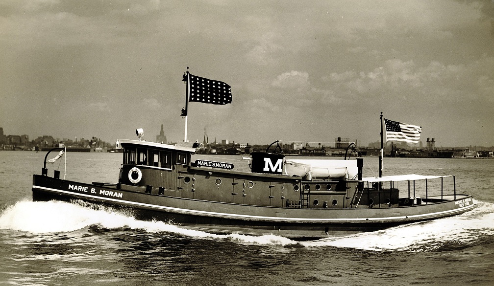
In 1936, Moran was operating a fleet of around 40 tugboats, from small Canal tugs, to larger ocean going and everything in-between. A new era opened in the fall of 1936 – The Marie S. Moran was launched. She would become Moran’s very first diesel powered tug.
Winton publicity photo of the brand new Marie S. Moran. Courtesy of the Dave Boone Collection.
The Marie would be powered by a single direct reversing Winton 6-164 engine, a huge 15”x22” engine making a mere 550HP at 275RPM. The 89’ tug was designed by Edmund J. Moran himself, and built at Pennsylvania Shipyards in Beaumont, Texas. The low profile tug was designed for use in the New York State Barge canal, composed of the Erie, Champlain, Oswego, Cayuga & Seneca canals, all of which required the low profile due to numerous low bridges and whatnot. When Marie S. Moran was constructed, Diesel engines were still being “figured out” so to speak, and companies would tend to try different engines and combinations. Like many tugs of the era, the Marie would be retrofitted with a retractable wheelhouse later in her life (more on this later), and the original Winton would be replaced with a more reliable 12-567 engine. The tug was sold foreign in 1961. Two more similar tugs would be built in 1937, the Eugenia M. Moran and Elizabeth W. Moran, powered by Alco-Sulzer engines. Both of these would also be sold foreign in 1950’s as well.
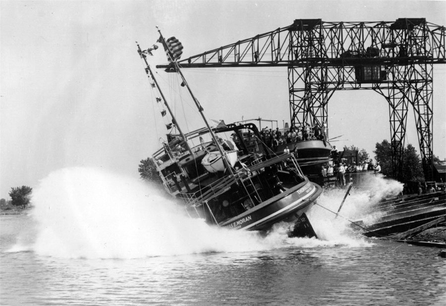
Skip ahead just a few more years to 1938. Electro-Motive, under GM introduced the new 567 engines, and Moran was looking for some more canal tugs, so the two would become one with the introduction of Thomas E. and William J. Moran. A new relationship would be born as well, Moran Towing working with Tam’s Inc. and General Motors.
The Thomas E. Moran on is on the slipways in Bay City, Michigan. It looks like both tugs were launched the same day! Click for larger. Courtesy of the Dave Boone Collection
The tugs would mark another milestone – breaking Tam’s, Inc. into the world of tugboats. While I do not know if they were the very first ones, they would be the ones that really set the pace. Tam’s was well versed in yacht design, as well as being a broker and insurance company. Working with Winton on yacht design would start the relationship with GM as well, being that GM now owned Winton. Beginning in 1938, and lasting for only about a year, General Motors marketed all three engine divisions (Winton {soon to become Cleveland}, EMC and Detroit) under the single “General Motors Diesel Engine Division”, even though the three companies were still operating individually.
The Thomas & William were featured in the 1940’s booklet “Diesel-Electric Vessels Powered by Cleveland Diesel”. Click for larger.
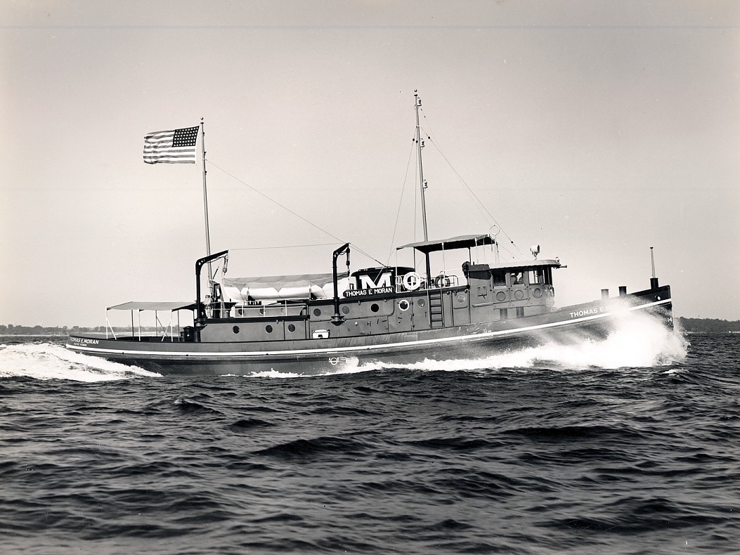
The brand new Thomas E. Moran on her sea trials, likely somewhere in Saginaw Bay. Click for larger. Courtesy of the Dave Boone Collection.
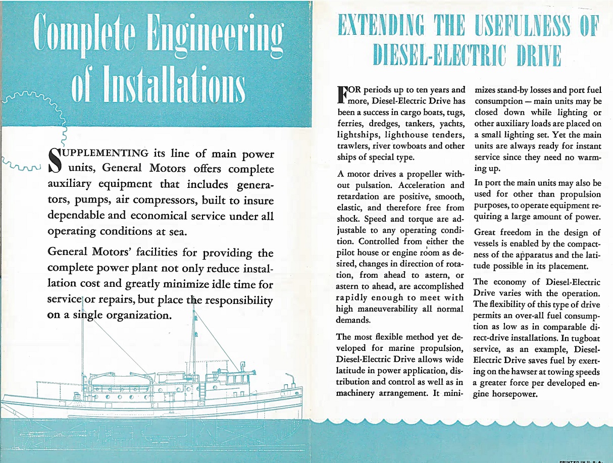
I was first introduced to the Thomas & William in detail when my partner in Cleveland research Jay Boggess showed me a scan of a GM booklet he had: “A New Conception of Diesel-Electric Drive”, which featured the two tugs in depth. Designed under Richard Cook at Tam’s, the tugs were 94′ 4 1/2″ long, with a 25′ beam. The all welded tugs were built in Bay City, Michigan at Defoe Boat & Motor Works. Diesel-Electric drive was not a new concept by any means, however using it with newer, medium speed engines was. Electro-Motive developed the new 567 engine in 1937 for railroad use, having learned from the lessons of the Winton 201A. However, interestingly enough, the first production 567 engines would be used in the Thomas and William, as quoted in EMD’s WWII era book “Diesel War Power”. The tugs used a pair of V8 567 engines, rated at 660HP at 750RPM each.
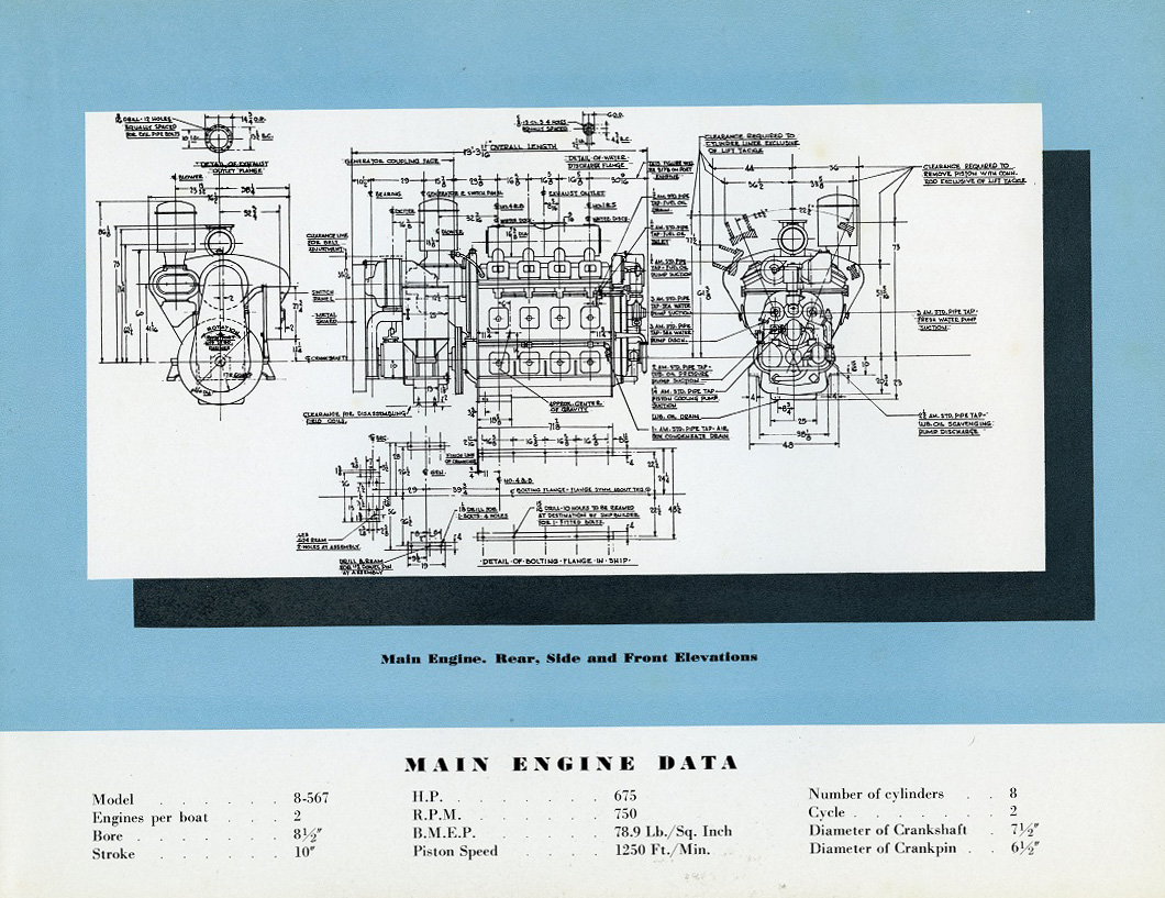
Photos of the engines from the “New Conception of Diesel-Electric Drive” booklet. Note how the engines do not look anything like the 567 we all know. While they did have a welded block, they did use more cast pieces in their construction, as well as individual covers for each power assembly. Click for larger.
Build sheet date for the engines. More on the name change shortly..
Thomas & William at home in the NYS Canal System. Click for larger. Courtesy of the Dave Boone Collection.
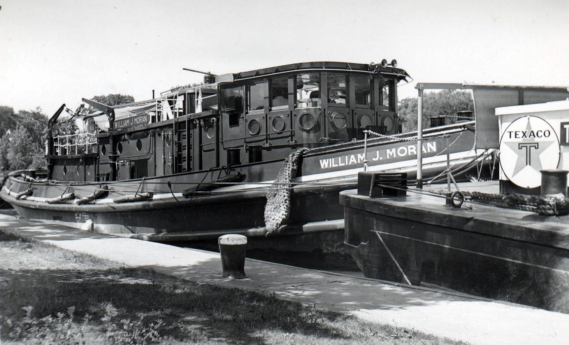
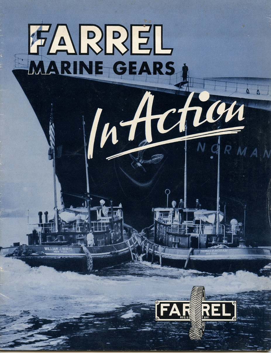
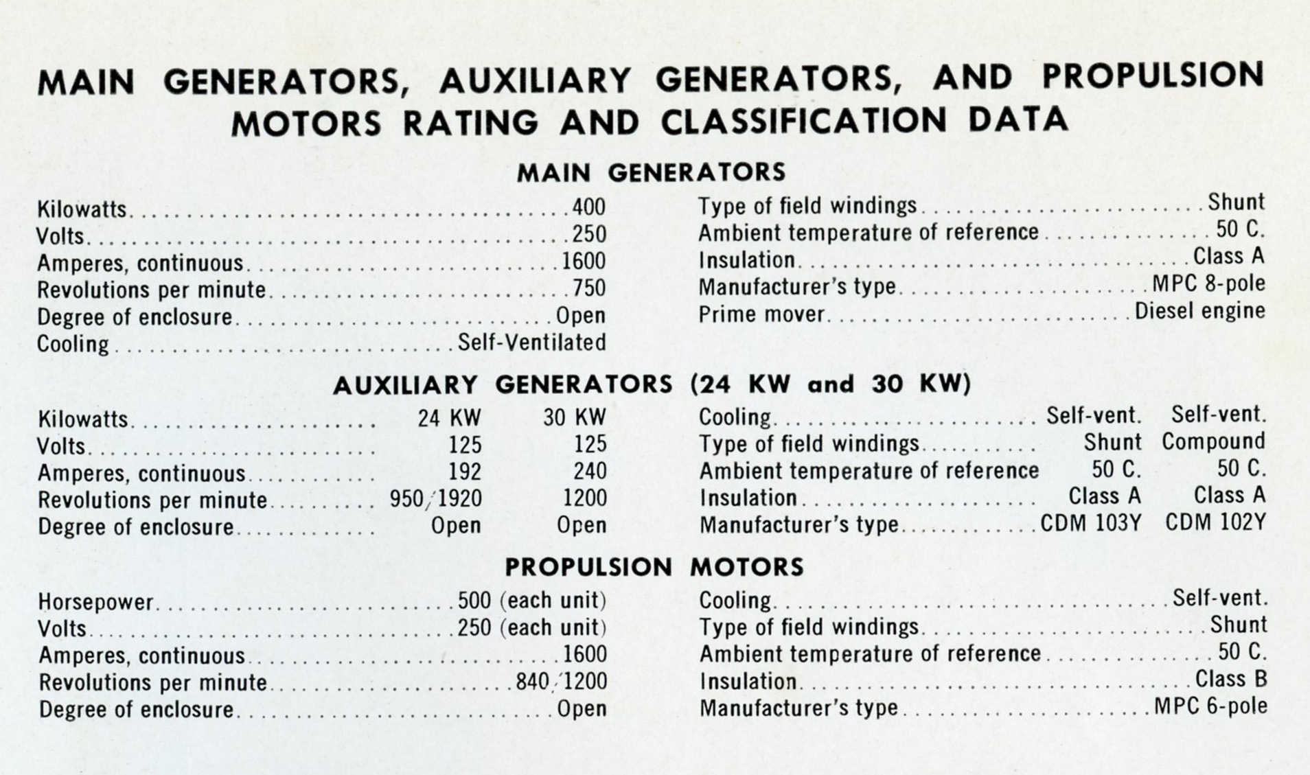
Electrically, the tugs used General Electric 400kW, 250 volt shunt wound main generators behind each of the 567’s, with belt driven 24kW exciter/shaft generators. General Electric also supplied the pair of 500HP propulsion motors. A common arrangement of the era was using two smaller motors, feeding into one reduction gear, supplied by Farrel-Birmingham. The arrangement was used on numerous fleet tugs throughout WWII. After the Thomas and William, Moran (along with James McWilliams Blue Line) would build several more tugs in 1939-1941 to virtually the same design, however they would be powered with single EMC 12-567 engines (Sagamore, Sheila Moran) and the last ones with Cleveland 12-278 engines (William J. Moran, Agnes A. Moran, Mary Moran, Sheila Moran), the later ones having a more normal, single level deckhouse (more on that later).
Farrel-Birmingham catalog pages showing the tugs. Click for larger.
Along with the 24kW shaft generators, the tugs each had a single Detroit 3-71, which drove a 30kW generator. The 71 was also a newly introduced engine in 1938. Click for larger.
A small booklet produced by GM featuring the new 567 engine. Ironically only the Thomas had the 567! Click for larger.
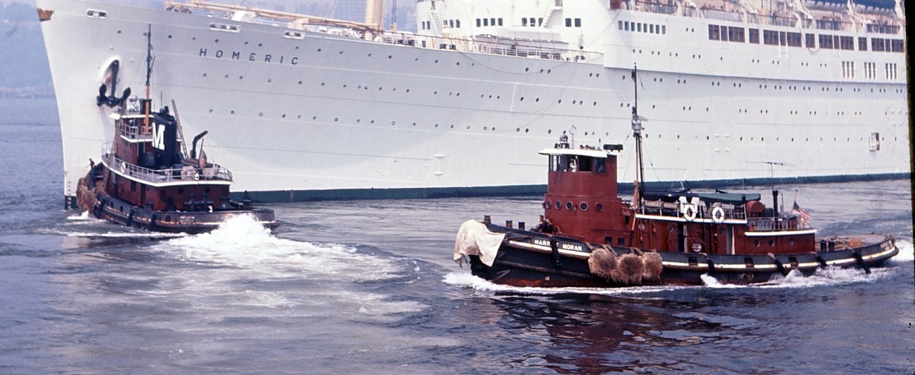
With World War II looming in the distance, the US Navy would requisition these tugs in 1940. I have long since been told that the Thomas and William were the prototype design for the YTB series that would be built in mass throughout the war. Part of me wonders if the Navy financed these in some way, with an agreement that they would be used during the war. But these details are likely lost to history. The Thomas would become the Namontack, originally classed as a Yard Net Tender (YN-46), Net Yender (YNT-614) and finally Yard Tug, Big (YTB-738). The William received the same treatment, and was named Wapasa, and also did time as a Yard Net Tender (YN-45), Net Yender (YNT-613) and finally Yard Tug, Big (YTB-737). After the war, the tugs would be returned (resold? I am not sure how those requisitions worked, if anyone knows, please drop me a line!) to Moran, however would be renamed. Originally the Thomas E. Moran, her new name was now the Harriet Moran. The William J. Moran became the Anne Moran.
The Anne Moran at home in the canal, made up in push gear with a grain barge (which looks to be an old motorship). The tugs had 4 control stations, the wheelhouse, the upper deck, the aft deck, and the engine room. Note the “box” on top. This was the upper wheelhouse to gain a little more height to see over the barge. The primitive wooden box was installed in the fall/winter and would fold up in inclement weather. Click for larger. Courtesy of the Dave Boone Collection.
After the war, Cleveland Diesel went heavy on marketing, producing numerous booklets and brochures. These are from the late 1940’s book “Commercial Vessels Powered by Cleveland Diesel”. Note that they used older photos of the Thomas and William, and airbrushed the original names out in favor of the new, post war renaming’s. Not only that, but they incorrectly spelled the one! An interesting feature of these tugs is the sliding heavy weather portholes, that would slide up the cover the large glass windows. Click for larger.
In 1956, Moran embarked on a modernization program for the canal tugs. The Harriet and Anne would both be repowered with single war surplus (from PCE vessels, unfortunately the records do not note which) Cleveland 1000HP 12-278A engines and Allis-Chalmers 814kW main generators, however the original propulsion motors were kept. Along with the repowering, the tugs received a new retractable wheelhouse. Introduced in 1950 by Lake Tankers Corp. on their tug Canal Cities, the retractable wheelhouse was a revolutionary advancement for working in the canal. A large air or hydraulic cylinder raised and lowered the wheelhouse to see over the barge, but to “duck” when a bridge or other obstruction was approached. Virtually all “modern” diesel canal tugs would be retrofitted with these by the mid 1950’s, with all new tugs being built with them from then on out.
Now with her new retractable house, the Harriet Moran would still work the canal, but by the 1970’s was regulated to doing assist and barge work in the harbor. The Harriet and Anne would keep their stepped deckhouses, and sliding “portholes”, however the other Moran canal tugs mentioned above would get more modernized single level deckhouses, and square retractable wheelhouses. Note that the new wheelhouse fits inside the profile of the original one. Even the original Marie S. Moran of 1936 was retrofitted with one! Click for larger. Courtesy of the Dave Boone Collection.
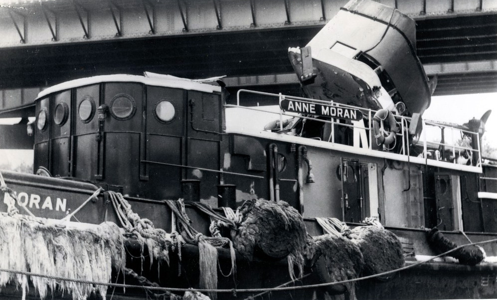
Unfortunately, working in the canal with a retractable wheelhouse had its downfalls. You need to pay attention! (To quote Buford T. Justice in Smokey and the Bandit: “Duck, or you’re gonna be talkin’ out yo ass!”) The wheelhouses essentially floated in a pocket, with some very basic guiderails. So when the captain forgets to drop the wheelhouse, the bridge is usually going to win, as what happened in 1965 to the Anne. Numerous canal tugs were decapitated over the years, but because they were so simple, the dents were pounded out, wires rerun, and back off to the races they went. I spent a few years working on a canal tug, and its an all hands on deck operation spotting for obstructions, especially high tension wires at night. Click for larger. VDD collection.
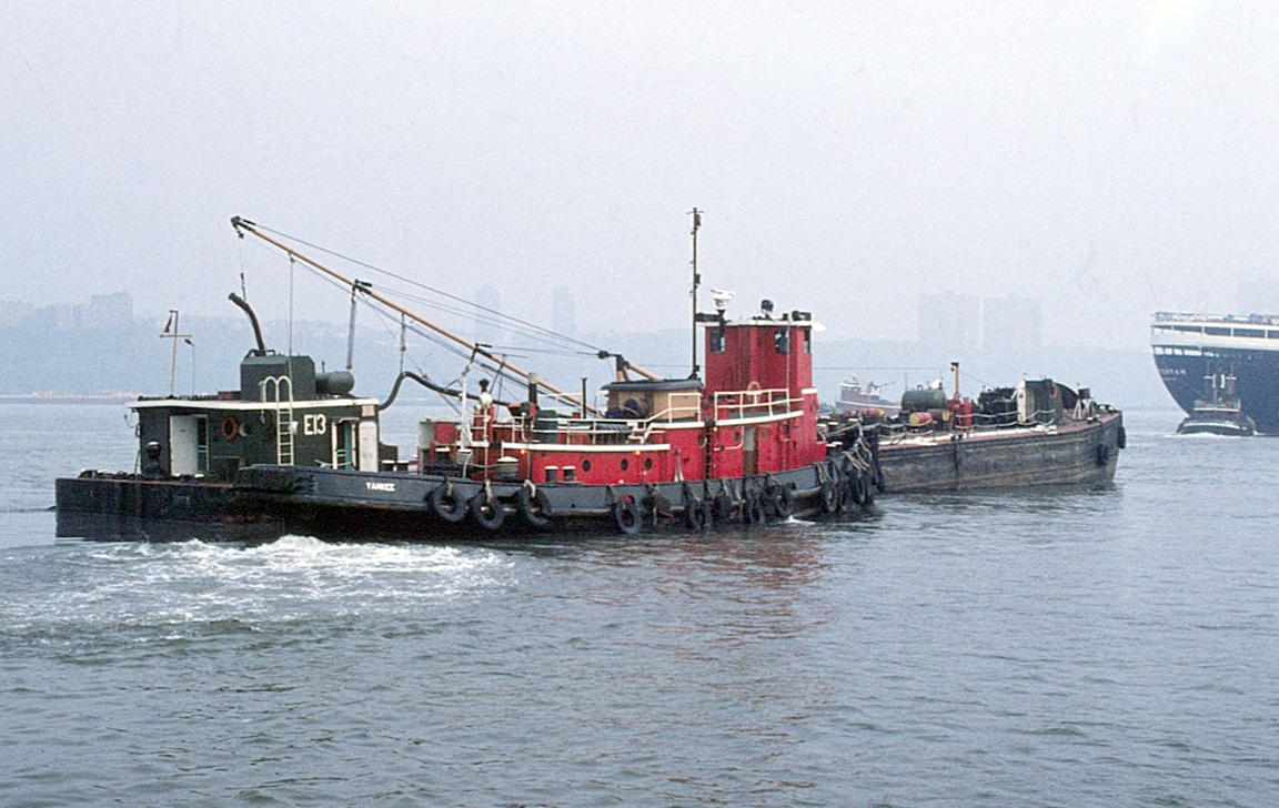
Typically a “last stop” for tugs working for Moran was to be put on the garbage barge run before being retired. The Anne is moving one of the DSNY scows in 1970.Click for larger. Courtesy of the Dave Boone Collection.
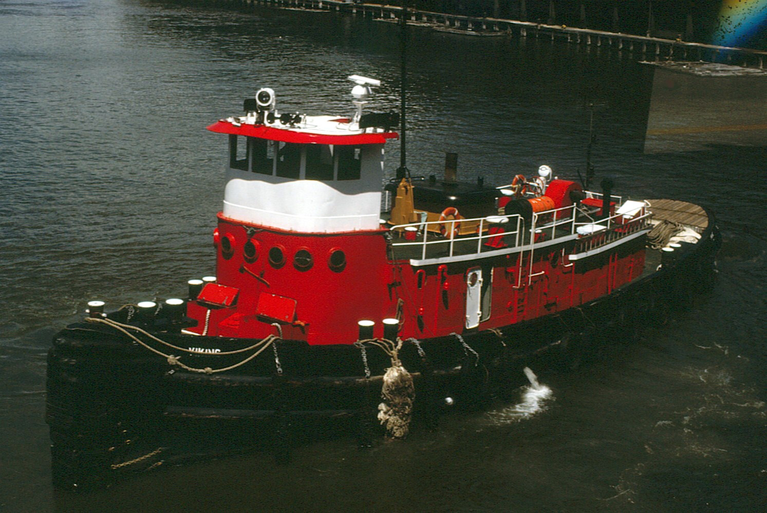
Moran would sell both of the tugs to Eklof Transportation in 1975/6 with the Harriet becoming the Viking, and the Anne the Yankee. Eklof would use the tugs for moving oil barges around the harbor for the next 15 or so years. Unfortunately, the road would end here for the Yankee (William J. Moran) and was scrapped in 1993. Our story does not end here though. Click for larger. Courtesy of the Dave Boone Collection.
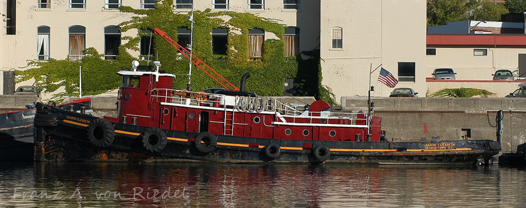
Now the McAllisters Sharon Elizabeth in Georgetown, SC. Click for larger. Photo courtesy of Franz A. von Riedel.
A small towing company, Georgetown Towing, based in Georgetown, South Carolina purchased the Viking, and named her as the Georgetown, doing ship and barge work in the area. McAllister Towing would purchase the company in 1999, and renamed the tug as the Sharon Elizabeth. Zenith Tugboat of Duluth, MN purchased the tug in 2005, and brought it up to the Great Lakes via the Erie Canal – right at home, 67 years after being built.
Now sporting Zenith’s stack colors, the Sharon Elizabeth is laying over in Troy, New York on her way to Duluth. Click for larger. Photo courtesy of Franz A. von Riedel.
Photo courtesy of Franz A. von Riedel.
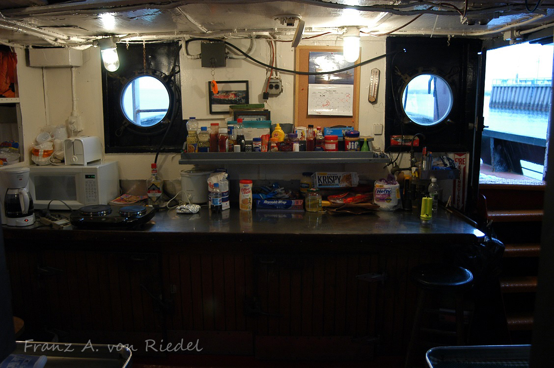
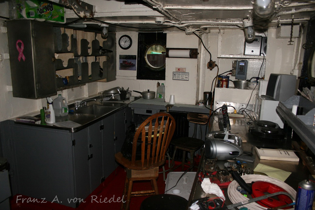
Lets take a quick walk through the Sharon Elizabeth, starting in the stern. I always wondered the reasoning behind the stepped deckhouse design. Entering in from the door, you head down a few steps into the galley, complete with giant cast iron Webb diesel stove that every tug and ship of the era had. Click for larger. Photos courtesy of Franz A. von Riedel.
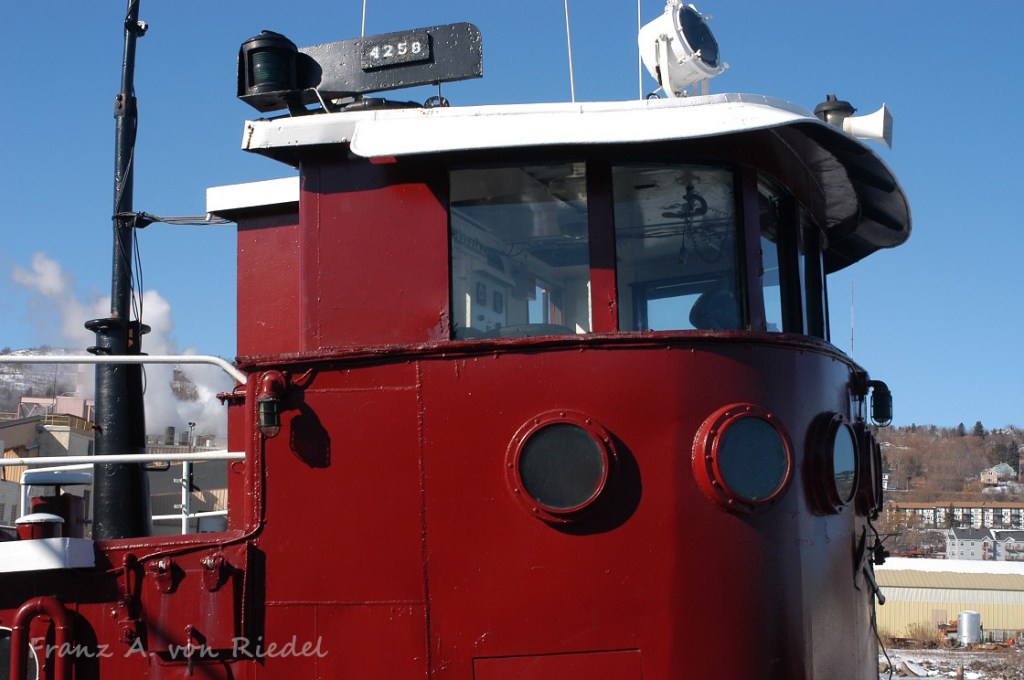
Canal tug wheelhouses are usually pretty spartan, simply because they lack any extra space. The Sharon’s wheelhouse had the typical Lakeshore Diesel-Electric control stands, and Benson electric steering, likely all installed during the 1950’s rebuild. Along the back wall is the running light panel, and the field amp/prop shaft RPM gauge and steering changeover switch. At some point in her life, Moran welded the sliding window portholes in a fixed position, and removed the tracks. It was not uncommon for canal tug wheelhouses to be kept in a semi-lowered position (especially when they get older and the system fails). The one on the Sharon is not all the way down here. Click for larger. Photos courtesy of Franz A. von Riedel.
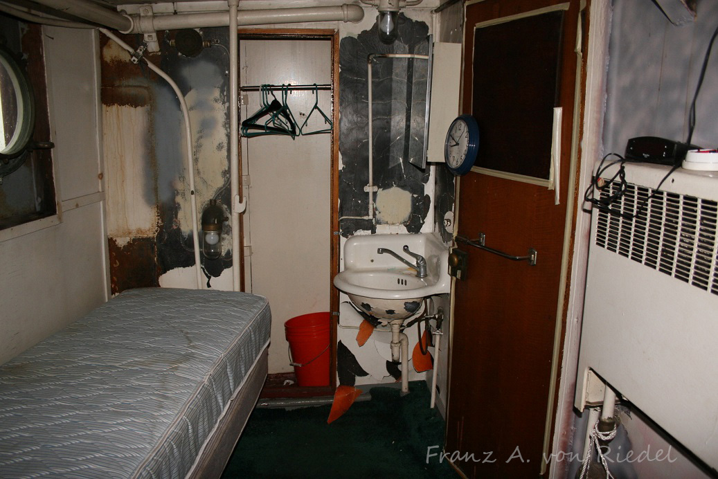
By the time smaller companies have these older boats, the staterooms are usually pretty tired – as often times the tugs are used as day boats, meaning no full time crews are living on the tug, which also means that maintenance starts to dwindle. For a canal tug however, these are some pretty big rooms! Click for larger. Photos courtesy of Franz A. von Riedel.
Photo courtesy of Franz A. von Riedel.
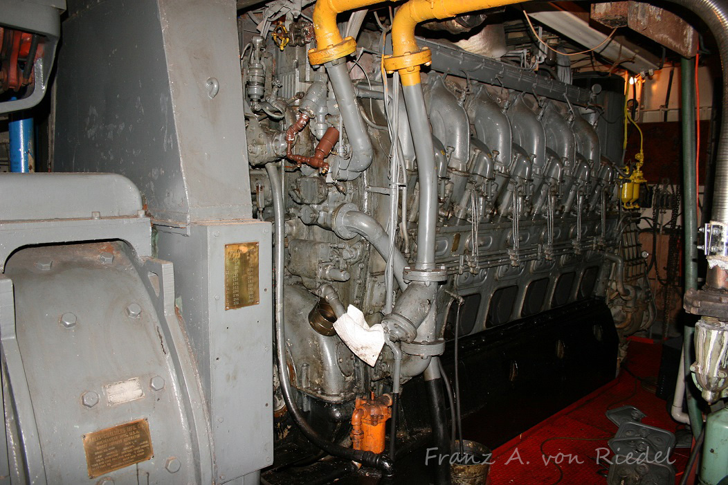
The Sharon had her twin 8-567 engines replaced in 1956 with a single Cleveland 12-278A removed from a Patrol Craft. An Allis-Chalmers main generator was utilized from a Destroyer-Escort, a common package used in Diesel-Electric tugs of the era. Click for larger. Photos courtesy of Franz A. von Riedel.
Electrically, the Sharon kept her original twin GE propulsion motors and Farrel-Birmingham reduction gear. A lakeshore propulsion panel connected the motors and generators. A Detroit 3-71 is seen in the forward end. Click for larger. Photos courtesy of Franz A. von Riedel.
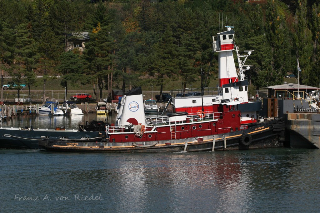
Zenith renamed the Sharon Elizabeth as the Statesboro in Spring of 2006. For an almost 70 year old tug at the time, she still looked sharp. Photo courtesy of Franz A. von Riedel.
The tug was sold in the fall of 2006 to Busch Marine of in Carrollton, MI. The tug is being towed by their own tug, the Gregory J. Busch. Photo courtesy of Franz A. von Riedel.
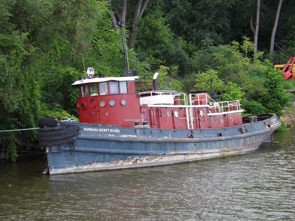
Busch Marine renamed the tug as the Barbara Merry Busch. The tug was tied up at their dock in the Saginaw River, only a few miles up from where she began her life in 1938. Unfortunately, the tug was never used by Busch, and she sits tied up listing heavily, waiting for what is likely an inevitable date with a scrapper one day. Even Busch’s large tug – Gregory J. Busch is laid up. This is another tug I would love to see inside, as she is powered by Alco 12-244 main engines.
Click for larger. Photos courtesy Todd Shorkey
Thomas E. Moran was featured in numerous GM advertisement’s.
While just a footnote in history now, the Thomas E. Moran will go down in history as being the first use of the EMD 567 engine, the engine that went on to become one of the most successful diesel designs even built, and used in countless tugs, locomotive’s and stationary applications. Moran would wind up working almost exclusively with Tams (and successor GM Design and Marine Design Inc.) over the next 30+ years, building some of the most recognizable tugs on the east coast – all powered with General Motors Diesel-Electric Drive. Following the Thomas and William, several 567 stationary gensets would be built, as well as a bunch of 12-cylinder models used in Navy and USCG tugs in 1939.
Many thanks to Franz A. von Riedel for sharing his photos of the Sharon/Statesboro. Thanks to Dave Boone for sharing numerous photos with me over the years, Todd Shorkey, Isaac Pennock & Jay Boggess as always for scanning and sharing more then I can recount.
Introduction – November 2021 – This was written by Jay Boggess in 2006 and originally titled “Adapting a Freight Loco into a Passenger Loco” and was presented at the Locomotive Maintenance Officers Association (LMOA) at their 2006 annual meeting. Back then, he was a manager with the Alaska Railroad. Before that, Jay worked at EMD for 22 years, which is now called Progress Rail. He has added some footnotes and clarifications after the 15 years since this was originally published.
This paper will describe a clever adaptation of an AC freight locomotive into a dual-service passenger/freight locomotive – the SD70MAC-HEP. It was a project driven (like many projects are) by an aggressive delivery schedule and design requirements. By taking several existing bits of locomotive technology, a unique and useful locomotive was developed and delivered in nearly record time for The Alaska Railroad.
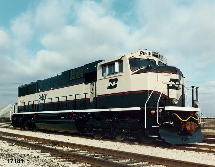
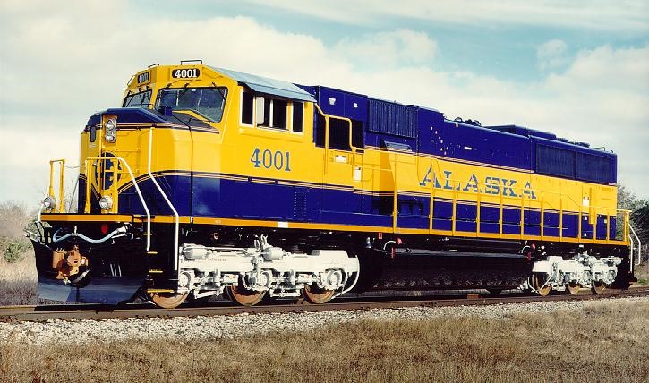
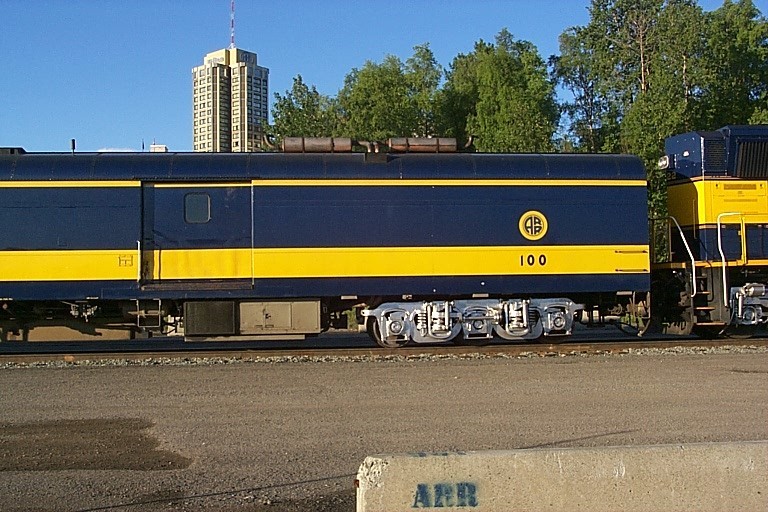
The SD70MAC-HEP has its lineage in 4 other EMD locomotives: Figure 1 is the first SD70MAC, delivered in 1994 to the Burlington Northern. Alaska Railroad purchased 16 units in a winterized configuration in March 2000, as shown in Figure 2.
Figure 1 – Burlington Northern SD70MAC
Figure 2 – Alaska SD70MAC
Figure 3 is the Long Island Railroad DE/DM30AC locomotive. This locomotive was the first EMD production passenger locomotive with AC traction motors, Siemens GTO inverters and inverter-based Head End Power (HEP) (the EMD F69PH-AC prototype units of 1989 never went into production, although many concepts initially tried out on the F69’s ended up on the DE/DM30’s).
Figure 3 – Long Island DE30AC
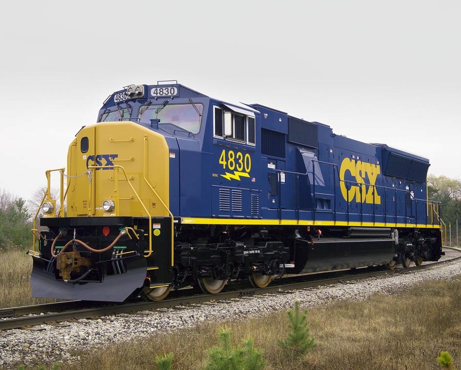
Figure 4 is the CSX 4300HP SD70MAC. This locomotive, designed and built just before the SD70MAC-HEP, put the Tier-1 emissions engine and cooling system onto a 70MAC for the first time. During its design, the equipment at the long hood end was extensively rearranged so that space could be allocated for the CSX-requested Eco-Trans Auxiliary Power Unit (APU). The space would later turn out to be key to the success of the SD70MAC-HEP.
These previous designs coalesced into the Alaska Railroad SD70MAC-HEP (Figure 5), a 4300 THP freight / 2400 THP-730kW HEP passenger locomotive.
I had an interesting perspective on this project: I was involved in the locomotive’s original conceptualization, design and build at EMD. I came to work for the Alaska Railroad soon after they were delivered and then was knee-deep in the post-delivery HEP system commissioning. Thus, when I need to complain to someone who designed this mess, all I have to do is to look in the mirror!
Figure 4 – CSX 4300-THP SD70MAC locomotive of 2003
Figure 5 – Alaska SD70MAC-HEP 4300 THP 730kW HEP
The Railroad:
The Alaska Railroad connects Anchorage (the state’s largest city) with Fairbanks, 356 rail miles north, along with the seaports of Seward and Whittier 114 and 72 miles to the south, respectively. Freight service consists of oil trains from the Flint Hills refinery at North Pole, Alaska to Anchorage[1], coal trains from the Usibelli mine near Healy to the port of Seward[2] and interchange cars from our barge operation in Whittier. Three trainsets of SD70MAC’s and hopper cars move aggregate from quarries in the Palmer-Wasilla area for construction in Anchorage all summer long. Our passenger season starts in mid May and consists of a mélange of trains:
The Denali Star – Two trains in daily service from Anchorage to Fairbanks, with stops in Wasilla, Talkeetna and Denali (Mt. McKinley). Eight ARR cars plus 8 to 10 cars owned by the cruise ship companies are pulled every day.
The Coastal Classic – One train to Seward and back, dovetailing with day cruises to Kenai Fjords National Park
The Hurricane Turn, with provides flag-stop service using RDC’s from Talkeetna to Hurricane, where a series of cabins are only accessible by rail.
Trains connecting cruise ship passengers from Whittier and Seward to the airport in Anchorage.
As tourism has increased, more cars are added, which is what started this whole project in 2001.
[1] The Flint Hills refinery shut down in 2014 and AkRR no longer moves jet fuel from Fairbanks to Anchorage.
[2] There is no longer any export coal out of Seward -just coal movements from Usibelli to Fairbanks and Eielson AFB.
HEP for our passenger trains was first handled by 2 paralleling 150-kW generator sets slung underneath the baggage car (see Figure 6). Later in 2000 and 2001, six GP40’s were rebuilt into HEP-equipped units for passenger service. 3009/10/11 were equipped with 300kW Detroit Diesel generator sets and 3013/14/15 with ex-Amtrak 800kW gear-driven generators. Each has their disadvantages:
The baggage car gen sets have limited capacity and susceptible to clogging with cottonwood lint.
The 300kW Geeps are noisy and again have limited capacity.
The 800kW Geeps (see Figure 7) are VERY noisy, have very small fuel tanks and are not at all fuel-efficient.
ALL the locomotives (even though recently rebuilt) are getting old.
Figure 6 – Baggage Car w/ undercar generator sets
Figure 7 – GP40-H with gear-driven HEP
As an answer to Alaska Railroad’s passenger power problem, EMD offered F59PH locos, but AkRR[1] considered them very expensive, especially for a unit that would only be needed in the summer. Robert Stout (AkRR CMO at the time) suggested to EMD, “We like what the SD70MAC does for us – what’s the possibility of putting HEP on a MAC?” Such a dual-purpose unit would be flexible for both the short passenger season and again useful the rest of the year as a freight locomotive.
When this suggestion wound its way to EMD Engineering, Tim Keck (EMD Manager of Systems Engineering at the time), posed that question to myself and others. We all realized that one of the two TCCs[2] of a SD70MAC might be modified to provide HEP, leaving the other TCC and truck to propel the unit (and the other truck just coasting). Consultations with our counterparts at Siemens confirmed that yes, EMD and Siemens could adapt the HEP transformer previously designed for the LIRR DE/DM30AC locomotive with the inverter of the SD70MAC to provide 480V 3-phase HEP.
As the original SD70MAC had no room in its carbody for the additional needed HEP equipment, several different ideas were proposed, including using the locomotive roof and running board. The only realistic hope was to dramatically shorten the fuel tank and sling the HEP equipment underneath the underframe. As the LIRR DE30AC HEP transformer was hung similarly under its structural carbody, this didn’t seem too bad of a situation. The challenge would be designing cabinets for the HEP switchgear for the underslung application. Design, cost and manpower estimates were made at EMD. But then, ARR decided not to buy locos for that calendar year – not completely forgetting the idea, just not for that year.
In the fall of 2002, CSX enters into this story. They came looking for new units – more SD70MACs like they already had – with 3 important differences:
The engines were hopped up from 4000 to 4300 THP[3].
By EPA regulations, they would be required to meet Tier-1 emissions and thus needed a new split cooling system (first applied to UP SD70DC units but never applied to a SD70MAC)[4].
CSX requested space be designed in the rear of the unit for an Eco-Trans APU[5]
[1] Alaska Railroad’s reporting marks are ARR. When the internet arrived, arr was already taken, so AkRR was used.
[2] SD70MACs have two Siemens-supplied Traction Converter Cabinets (TCCs). Each TCC is an electronic inverter that takes the DC output of the main generator and chops up the DC into 3-phase variable voltage, variable frequency AC for 3 axle-hung induction motors of one truck.
[3] The 16-710G engine of the original SD70MACs are rated at 4000 Traction Horsepower (THP) at 900 engine rpm. By spinning the same engine to 950 rpm, 4300 THP can be realized. Traction horsepower is the power delivered to the main generator.
[4] The cooling system of a locomotive has to remove heat from water used to cool the diesel engine cylinders and lube oil system (“jacket water”) and the water used to cool the compressed air leaving the turbocharger (“aftercooler water”). By utilizing two separate radiators with separate cooling fans and water pumps, the aftercooler water can be kept around 110 F while the jacket water can be kept at 180 F, improving emissions and engine performance.
[5] APU – Auxiliary Power Unit – a small diesel to keep the coolant water warm and the batteries charged when the main engine is shut down.
By some creative re-arranging of components, a volume of 3’6”x6’x5’9” was created for the APU by:
Replacing the 4-cylinder WLA electric drive air compressor with a shorter direct-drive-only WLN 3-cylinder compressor.
Rotating the #2 TCC 180 degrees so that its “blind side” faced aft (the Siemens TCC has one face with no access doors for maintenance). This put the access door for the TCC computer in the same room as the air compressor – less than desirable but acceptable.
Moving the battery box from the conductor’s side to engineer’s side of the long hood.
As always, EMD Drafting worked quickly to deliver the necessary production drawings to the shop for a December 2003 start of construction. CSX would eventually acquire 130 4300-THP SD70MAC’s.
With the CSX Tier-1 70MAC design complete, EMD realized that the CSX APU space could easily morph into a location for an Alaska HEP system without shortening the fuel tank and without slinging transformers and equipment underneath the loco. This proposal was offered up to Alaska in the spring of 2003.
Now the problem became one of delivery schedule – Alaska needed locomotives by April/May 2004, so as to avoid leasing locomotives for the 2004 summer passenger season. However, the lead time for the Siemens-supplied software and equipment for HEP prevented such a schedule (although they could easily deliver freight-only equipment for an April 2004 ship date). Around this impasse, EMD came up with the idea – deliver the locomotives without HEP capability for April 2004, then install the HEP equipment later. With that compromise, Alaska signed for 8 SD70MAC-HEP locomotives in June 2003 (up from the 4 units they were originally considering). This was a very ambitious design/build schedule for Electro-Motive.
After settling details with the railroad in July 2003, it was time for EMD to translate wild-hair, back-of-the-envelope ideas into something that could actually be assembled in London (ONT) – and assembled in time. The key problem was this: how to shove ten pounds of…stuff into an eight-pound bag! The design process for the Alaska HEP was fraught with limited time, false starts and changing concepts. We knew that the transformer could not be delivered until August 2004, but then we realized that the more equipment we could mount in the HEP Equipment Room in London, the less work that would be required to do in Alaska and the better for all parties involved.
The System
The final arrangement for the SD70MAC-HEP ended up as follows:
Siemens GTO TCC cabinet with modified software in Siemens ASG computer (ASG: Antreib Steuer Gerät – German for “Propulsion Control Apparatus”)[1].
Repackaged HEP transformer, based on LIRR transformer design.
Three delta-connected capacitors for AC harmonic filtering – 550 kVAR (capacitive) total.
Switchgear to switch modes between HEP and traction and to disconnect the #1 end HEP receptacles.
HEP blower and filter behind the long-hood headlight.
Main HEP contactor (ACC) and sundry HEP contactors, relays and equipment.
HEP switches, pushbuttons and fault lights located in cab on HVC[2] door.
Most of the equipment ended up squeezed into the volume that was created for the CSX APU, which was renamed the HEP Compartment. Figure 8 is the outside of the HEP Compartment; Figure 9 is the inside and Figure 10 is a one-line diagram of the HEP system.
Figure 8 – Outside View of HEP Compartment
Figure 9 – Inside View of HEP Compartment
Figure 10 – One-Line Diagram of the HEP System
[1] When designing the first production BN SD70MACs in 1993-94, we had duplicate names: TCC for Traction Converter Cabinet and TCC for Traction Control Computer. To avoid confusion, we decided to use TCC for the whole Siemens inverter and the German abbreviation ASG for the Siemens computer alone.
[2] HVC – High Voltage Compartment, this forms the back wall of a EMD cab.
Siemens TCC
The Siemens TCC (Traction Converter Cabinet) required limited hardware yet extensive software changes to accommodate HEP. The TCC hardware went through a redesign in 1999 and is identical to TCC’s that were built since that redesign, except for Alaska-specific cold-weather modifications first applied on Alaska’s previous SD70MAC order and reused again on the SD70MAC-HEP[1].
Small changes were required to the ASG hardware. The chassis required a half-dozen wire wrap mods and one PC board needed a capacitor and resistor so that the unit could monitor the 480V HEP output for closed-loop voltage control.
The largest single change was new software for HEP. “New software” was not the correct phrase – “extensive additions to existing software” is much more appropriate. The ASG processor is nearly unchanged from 1992 and its software written in assembly language. In spite of all the new code, the version software written for the Alaska HEP TCC’s is backwardly compatible with every other Siemens TCC.
When in HEP mode, the TCC is programmed to switch the GTO’s at about 400 Hz to create a stepped 60 Hz (fundamental) 660V output, which is then fed to the HEP transformer. The TCC can generate the 60 Hz under widely-varying DC Link voltages. At lower HEP loads, only 1050V (dc) is required, which the diesel engine/main generator can handle at TH2. Full HEP load can be supported with TH3 and 1250 V(dc). As the engineer changes his throttle, the TCC adapts to the changing DC link voltage and continues to deliver constant HEP voltage and frequency.
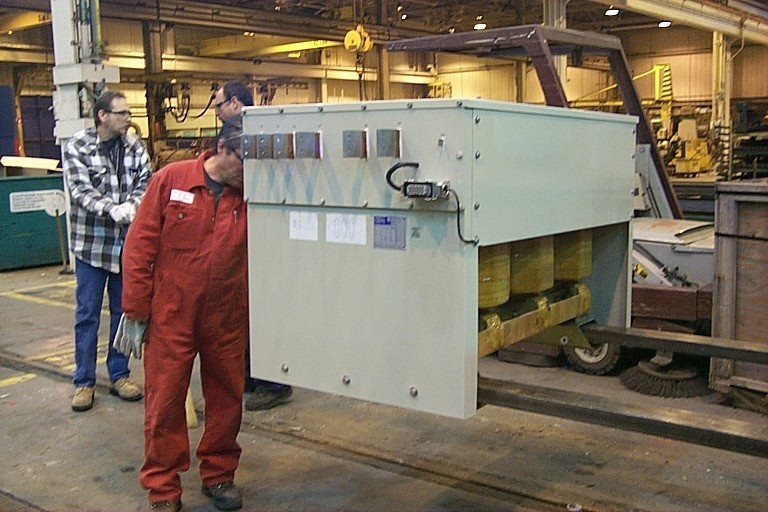
HEP Transformer
The HEP transformer (Figure 11) serves to isolates the 2600V(dc) world of the DC Link from the 480V(ac) of the passenger cars. It is of 939 kVA capacity wound with a delta primary and wye secondary (nominally 660V line-to-line in, 480V line-to-line out). The neutral of the secondary is connected to a HEP ground relay for ground fault detection. It was manufactured by Trafomec of Italy to Siemens specifications and wound with a series inductance to form the “L” of an L-C harmonic filter. The core is practically identical to the LIRR transformer except for better insulation to avoid water issues painfully learned on Long Island.
Figure 11 –HEP Transformer on forklift blades
The original Long Island HEP transformer (known as TAPS) consisted of a single underslung package that combined transformer core and harmonic filter capacitors. It was set up so that its cooling air came from the traction motor plenum, which was pressurized by air that first cooled the LIRR inverter phase modules and exhausted out the sides.
For the SD70MAC-HEP, the transformer core was placed in its own package and capacitors mounted separately in the HEP compartment. In Figure 11, you can see the first HEP transformer in London, supported by long forklift blades for installation across the walkway at the left rear of the locomotive. The transformer windings can be seen just above the blades, which is also the warm air exhaust to the transformer. The sheet metal plenum surrounds the top and sides of the core, but is open on the bottom, forming a sheet metal “skirt” around the base. This skirt aligns with 2” x 2” foam held in place by channels on the floor of the compartment, forming a tight air seal for the exhaust air. Four holes in the two forklift tubes mate with threaded holes drilled into steel bars precisely aligned onto the underframe. Guide pins were temporarily threaded into the mounting holes to guide and align the transformer installation. The back pins and hold-down bolts were reached by removable access plates in the transformer plenum and lower battery box.
The first transformer was air-shipped from Italy to London Ontario in May 2004 so that it could be fitted into the last locomotive while still under construction. Several minor dimensional problems were discovered in the process, justifying the efforts folks at Siemens and EMD went through to get the transformer delivered in time. The problems found were then corrected on the seven remaining units still in Italy, greatly streamlining their installation in Anchorage.
As bulky and unwieldy as the 3500-pound transformer appears, the Alaska Railroad mechanics, electricians and forklift operator quickly became adept at the transformer installation.
[1] Jay was involved in the first order of Alaska SD70MACs back in 1999. EMD put heaters and insulation all over the locomotive to allow the loco to survive at -40oF below and colder. The Siemens inverter uses a fluorinated hydrocarbon to cools its power electronics that turns to Jello below some low temperature. There are electric heating elements to keep that from happening in any throttle position.
Harmonic Filter Capacitors:
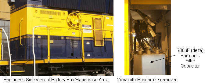
The three HEP harmonic filter capacitors are mounted behind the locomotive handbrake (Figure 12). This handbrake was redesigned so that the entire brake was mounted on a large removable vertical steel channel[1]. This way, the brake chain could be detached and the assembly could be lifted out with a crane on the very rare occasions that the capacitors had to be accessed. The three capacitor cans form the “C” of the L-C harmonic filter. Each can consists of three 700-microfarad capacitors connected in delta and all three cans are connected in parallel to the transformer busbars.
Figure 12 – Harmonic Filter Capacitor
As soon as the HEP system starts up, 220 amps circulate between each of 9 capacitor terminals and the HEP transformer. This adds up to 660 amps per phase and 550 kVAR (kilo-Volt- Amperes-Reactive), leading power factor. Under full load (730kW, 878amps at 1.0 power factor), the inverter HEP system delivers 480V with 2.7% total harmonic distortion (THD). The resulting current THD is 3.9%. The worst-case voltage harmonic is the 7th (420Hz) at 1.7% of the fundamental.
An interesting effect of the capacitor bank shows up when summer-type loads (air conditioner compressors and blowers) are powered by the HEP system. During cooler weather, HEP loads are mostly heaters and cooking equipment and thus nearly unity (1.0) power factor. In that situation, the TCC has to handle the real current of the load plus the 660 amps of capacitive current of the capacitor bank. In the summer, the load is much more inductive at ~80% power factor. The leading capacitor current cancels the lagging inductive current of the compressor and blower motors. This lessens the amperage the TCC has to handle (the TCC being a peak-current limited device) and actually allows for another 110kW of HEP capacity at lagging power factor[2].
[1] The handbrake was portable/removable in the same way a 1960’s portable TV was portable because it had a handle! When the handbrake was removed for capacitor work (which happened in 2008 on the second order of 4300’s when the capacitor connections overheated due to poor nut torquing), the AkRR mechanic Dave Church placed another unit downhill from the MAC, tied down the brakes and ty-wrapped the couple cut levers. Anchorage yard has a downhill north-south grade and he was NOT going to let that MAC run away!
[2] AkRR has NEVER approached the HEP capacity of the SD70MAC-HEP with any passenger train it has pulled.
Switchgear:
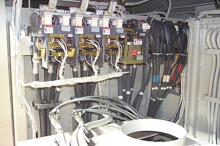
The HEP/TM switchgear (Figure 13) has two functions to perform:
Switch the output of TCC#2 from either the three rear truck traction motors or the HEP transformer.
Disconnect the #1 end HEP receptacles so that they are electrically dead when HEP is not required out the lead end of the locomotive (known as TLD for train line disconnect[1]).
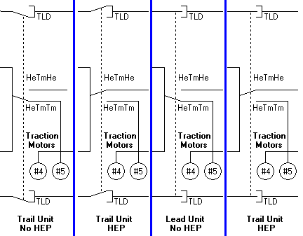
In most HEP locomotives, these functions are handled by two separate motor-operated switchgears. Roberto Michelassi of Elcon, Inc suggested a method where one switch motor could handle both functions. A five-module switchgear is mounted on mounting plate bolted to aft end of TCC2. Two switch modules switch the TCC output from traction motors to transformer. The other 3 heads handle TLD function. The switch modules are equipped with motor cut out solenoids (just like the switch modules used on an EMD DC locomotive to isolate traction motor fields). When it is desired to disconnect the #1 end HEP receptacles, the solenoids are energized, and the switchgear rolled back and forth to center the switch fingers on the TLD switch modules. Figure 14 illustrates the four possibilities that correspond to the four modes of HEP/Traction.
Figure 13 – HeTm Switchgear
Figure 14 – Four modes of HEP/Traction
[1] Somewhere through the history of locomotive Head End Power, someone figured that the front receptacles ought to be electrically dead when not needed, so as not to compound problems if a passenger loco hit an automobile in a grade crossing accident.
HEP Blower and Filter
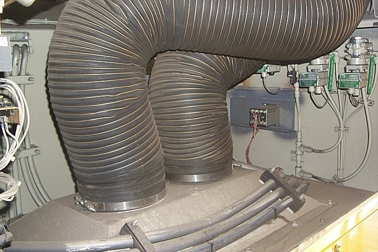
The HEP blower was no exception to the challenge of trying to get all the HEP equipment into the space available. At one point of the design cycle, we even considered dispensing with the blower entirely and using dampers to allow traction motor air to cool the transformer. In the end, EMD found a small 480-V blower that would fit high in the long hood, right behind the headlight (see Figure 15). This blower draws air from a grill high on the engineer’s side just aft of the radiator hatch and discharges to two 10” flexible ducts that route to the top of the transformer (Figure 16)[1]. The air out exhausts out a labyrinth grill just above the walkway, designed to prevent wash water entering the transformer compartment (Figure 17). The blower and motor are mounted to a removable roof hatch bolted to the end of the long hood.
Figure 15 – HEP Blower Air Intake
Figure 16 – Flexible Ducts to top of HEP Transformer
Figure 17 – Transformer Exhaust Grill
One interesting, unexpected concern that didn’t arise until the locomotives arrived in Alaska was cottonwood! Up and down the Railbelt in June and July, cottonwood lint wafts through the air. The lint can be so bad that during the height of the season, undercar gen sets (the cruise train companies have their own generators) need their filters changed twice from Anchorage to Fairbanks. This problem was pointed out by ARR senior electrician Gary Odens and a solution was quickly found. The HEP blower air intake is nearly the same size as the 25” x 16” x 2” carbody filter used on our MP15’s. ARR boilermaker Jim Blakely quickly came up with an easy-change filter holder that would bolt on to the air intake (Figure 18).
Figure 18 – HEP Blower Paper Filter Installation
Fortunately, the conservatism in the HEP blower design paid off here. As EMD was uncertain of the pressure vs volume characteristics of the repackaged HEP transformer, the air flow engineer over-designed the HEP blower. Thus, there was plenty of static pressure for the air filter and still allow for sufficient cooling air thru the transformer.
The blower is controlled by temperature sensors inside the transformer. Three 100-ohm RTD (resistance temperature detectors) sensors are installed in the windings. These are read by the TCC#2 computer and fed to the EMD computer, which turns on the blower when any sensor is hotter that 115C and then turns off the blower when all sensors are below 75C.
[1] We dubbed these flex ducts “Snuffy Trunks”, after Mr. Snuffleupagus of Sesame Street.
Remainder of the Equipment:
The rest of the electrical equipment was wedged into the space available. A small cabinet was set into the long hood aft of the radiator hatch and was dubbed the Small HEP Cabinet (appropriately enough). Figure 19 shows the cabinet. It contains the contactor and circuit breaker for the HEP blower, the HEP Ground Relay, a Train Line Voltage relay (prevents the main contactor from closing or the HeTm switchgear from moving if the external HEP trainlines are energized) and a pilot relay for the big ACC main contactor.
Figure 19 also shows the rest of the ancillary equipment. The Potential Transformers (PT’s) are 100:1 transformers that provide voltage feedback of two line-to-line HEP voltages to the Siemens ASG. An “old-fashioned” Under-Over-Voltage relay serves as a hardware backup to open the ACC if the voltage control of the TCC fails. The main ACC contactor is partially obscured by the HEP air ducts. This is rated at 1200 amps and is equipped with CT’s and a thermal overload element. Both are somewhat redundant as the TCC quickly acts to cease HEP whenever there is an overload or short circuit in the passenger cars.
Figure 19 – Small HEP Cabinet
HEP Controls:
The HEP controls for the SD70MAC-HEP were, in some ways, a step forward into the past. The LIRR DE/DM30 uses several Display screen menus to control its HEP system, but very early in the design process, Dennis Melas (EMD Software Systems Manager) told me, “You know, I can pay for a lot of switches and pushbuttons before I can justify spending man-hours to write code for more menus—especially for just 8 locomotives!!!”
So instead, we used the old EMD “eggcrate” lights for status and fault information (controlled by the computer), pushbuttons for start, stop and fault reset (read by the computer) and a multi-deck 4-position rotary switch for the HEP/Traction mode select (this also handles the convoluted Train Line Complete logic). Instead of digital or analog meters for voltage and current, a Display default meter screen is just one FIRE screen button press away. Thus, we made a control panel that’s a combination of the look and feel of our older GP40-H locos. Moreover, we also duplicated the pushbutton/light sequence of the GP40-H as well. The montage in Figure 20 illustrates the back wall panel and engineer’s station display.
Figure 20 – Montage of HEP cab controls
Conclusions:
The results of this project are eight versatile passenger/freight locomotives – ARR 4317 through 4324. When the HEP system is off, the unit is a 4300-THP locomotive. With HEP on, it is a 2400-THP, 730-kW HEP locomotive. Moreover, it can deliver that HEP load in TH3 (490 rpm) and up to 270kW HEP in TH2 (370 rpm). An F40PH or GP40-H in contrast would run at a constant 900 rpm to deliver the same HEP.
The system has turned out to be very reliable. If the 710 engine starts, then HEP is available. There is no pony engine to service and thus no pony engine cooling system, fuel system or lube system to deal with. The only filter to change is the HEP blower filter and so far, the cottonwood lint at 15 feet off the rail has been very manageable. The only failures have been one HEP blower contactor and one broken switch module.
Presently, we have four 4300’s on our Anchorage-Fairbanks daily service. Two units leave Anchorage and two leave Fairbanks every morning at 8:15. One unit in each consist provide HEP and 2400 traction horses, the other provides full 4300 THP.
Last summer (2005), one 4300 handled the Seward Coastal Classic train by itself, but this summer the train gained two cars, putting it outside our comfort zone of a single 4300 making HEP and pulling the 3.0 percent grade approaching Grandview. So, we put our older P30 power car (a 4-axle ex-E9B) and a 4300 making full traction. Our cruise train service from Seward, Anchorage airport and Whittier is handled by another 4300 and our P31 cab/HEP power car.
The MAC’s making HEP do have a unique sound – the switching of the inverters produces a distinct “EEEEEEEEEE” pitch at about 400 Hz, very noticeable when standing right next to the TCC#2. In terms of sound levels, the whine of the MAC is 82 dBA at 20 paces versus 85 dBA of a GP40 in HEP mode. But a single-tone whine is much less objectionable than the roar of a 900rpm 645 engine!
The HEP system efficiency turned out to be a bit of a surprise when finally tested. Efficiency was never a contract requirement, but upon testing we found that full-load efficiency was only about 88%, rising to 92% at part loads. This represents nearly 100kW of losses at 700kW load. Consultations with Siemens revealed that part of the poor efficiency was due to the limitations of the TCC computer. The LIRR computer has a more modern processor so that more efficient switching pulse patterns could be selected. These could not be realized with the SD70MAC TCC computer.
But in many ways, the “poor” efficiency is of little consequence. Seldom will we see large 700kW HEP loads. To improve that efficiency would require more copper and more steel in the transformer. That in turn would cost more money and demand more space in an already crowded locomotive – even if there was money to do a redesign! Thus, the poor efficiency really is just an acceptable result of a logical engineering trade-off.
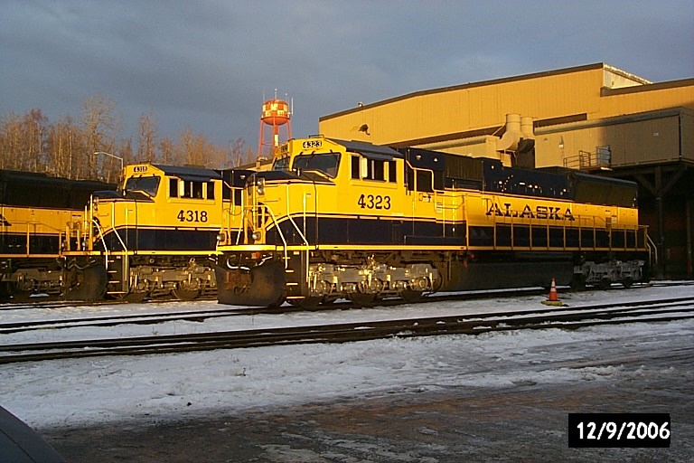
The SD70MAC-HEP units arrived in Alaska in April and May 2004 and immediately started pulling freight and passenger trains (with HEP provided by other means). HEP transformers were installed in September-December 2004. EMD and Siemens engineers arrived in October 2004 to test and commission the HEP software. Limited runs with the HEP system running were made on our weekend Aurora trains starting in January 2005. After correcting one extremely annoying software bug in the spring, the units entered day-in/ day-out on May 15th of the same year. I see no reason to expect them not to be running 20 years from now (Figure 21).
Figure 21 – SD70MAC-HEP on first day of 2005 passenger season
Contributions:
All photos and diagrams are by the author, except for Figures 1, 2, 3 & 4, which are EMD photos from the collection of Jay Boggess.
The Alaska HEP project had many participants; all who deserve recognition and all who without their help this project would not have succeeded: Ulrich Foesel, Hartmut Wagner and Horst Nowy of Siemens: Ulrich was my counterpart at Siemens, Hartmut was the software engineer on TCC’s and Horst was the long-time service engineer in Alliance, NE, who did the ASG hardware mods.
The following Electro-Motive folks: Dennis Melas (software manager), Curtis Montgomery (software engineer) and Margaret Foltz (software testing). These three had to translate, write and test the code for 70MAC HEP.
Forrest Green (systems engineer): He and I worked together (along with many design/drafters) to get the 10 pounds of stuff into the HEP compartment of the 70MAC.
Todd Lail (systems engineer). He got to pick up the pieces after I left EMD for Alaska.
Tony Bladek (lead engineer for LIRR DE/DM30) and Craig Prudian (systems engineer); Both whom I bounced many ideas off of, especially in the fields of passenger locomotives and Head End Power systems.
Plus, dozens of others at EMD in LaGrange and London who pushed pencils, swung wrenches, found wayward parts and translated barely-dry drawings into a completed locomotive.
Roberto Michalessi and Frank Garrone of Elcon, Inc (Minooka, IL): We worked together on the 2002 incarnation of Alaska HEP when EMD thought we’d mount HEP equipment beneath the underframe. Elcon didn’t get to build the cabinets for the final version but did build some subassemblies.
The electricians, machinists and boilermakers at the Alaska Railroad who installed the HEP transformers in Anchorage and helped commission the HEP system.
Finally, Tim Keck and Dave McColl of EMD and Robert Stout, formerly of the Alaska Railroad (now with Colorado Rail Car); the idea of the SD70MAC-HEP first germinated in their minds. I and everyone else just watered the seedling and let it bloom.
Postscript November 2021 – Alaska RR bought 4 more SD70MAC-HEP locos in 2006, which were delivered to Alaska in 2007. ARR 4325 – 4328. Combined with the first 8 HEP MACs and the original 16 4000THP SD70MACs means that AkRR has 28 6-axle AC locomotives.
Jay Boggess left AkRR in 2010 to work on hydroelectric dams for the U.S. government.
General Motors sold the Electro-Motive Division in 2005. The new owners renamed it Electro Motive Diesel. Caterpillar through its subsidiary Progress Rail purchased EMD in 2010 and Progress Rail eventually dropped the EMD name.
Many souls Jay worked with at the time have now retired and some have since passed away.
Thanks as always to my cohort in Vintage Diesel Design Jay Boggess for sharing and updating this fantastic look at these locomotives. While no, I guess a 17 year old locomotive is not technically “vintage”, it is of course an important part of EMD’s vast history.