It was sad to hear that this past week, the tug Pegasus made her last trip to the great shipyard in the sky. Figure I would throw together a little post about a cool old vintage tug that would meet an unfortunate end this week.
The Pegasus was built in 1907 by Skinner Shipbuilding in Baltimore, for Standard Oil Company, as the S.O. Co. 16. The tug would later be renamed the Socony 16, and eventually wound up as the Esso Tug #1 after several rounds of company reorganizations. McAllister Towing of New York would purchase the steam powered tug, and rebuild her. Converted to Diesel propulsion, an EMD 567 was installed in place of the large engine and boiler. Now renamed the John E. McAllister, she would join the companies massive fleet doing shipdocking and other harbor work. McAllister would also purchase sister tug Esso Tug #2, and rebuild her the same way, now renamed as the Roderick McAllister. Another Socony sister tug – the Socony #14, would find a new home with Philadelphia’s Independent Pier Company, and was renamed the Jupiter. She also is a museum tug in Philadelphia.
Unknown photographer, Courtesy of Dave Boone
Ernie Arroyo Photo, Courtesy of Dave Boone
By the 1980’s, towing companies were selling off the last of the older, converted steam tugs. Numerous smaller companies would benefit from this, and would give many of these older tugs a new life. In 1987, the John E. McAllister was purchased by Hepburn Marine Towing of New York, where she was renamed as the Pegasus.
Photo by Jay Bendersky
Photo by Jay Bendersky
Hepburn Marine would do various work throughout the city, including spending several years towing carfloats for the New York Cross Harbor Railroad. Hepburn would ultimatly charter the tug James E. Witte from Donjon, the former Central Railroad of New Jersey tug Liberty for doing this work – a tug much better suited. Pegasus would be retired in 1997.
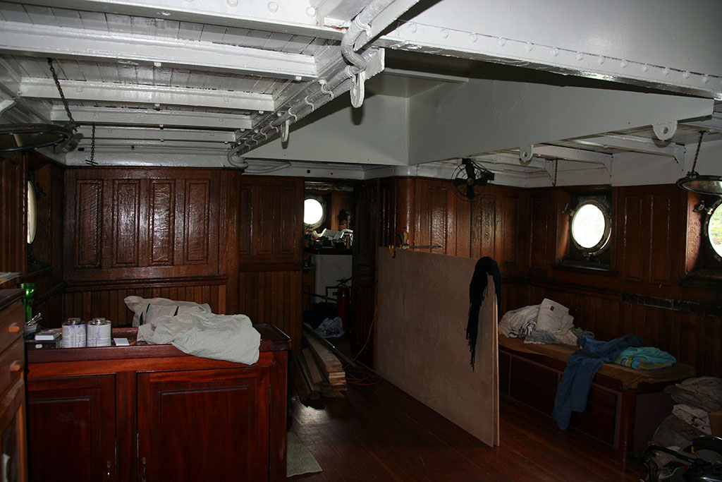
The Tug Pegasus Preservation Project was formed, and spent many years actively restoring the tug from the hull up. Volunteers spent several years actively restoring various parts of the tug, and the Pegasus would tow the Lehigh Valley Barge #79 (The Waterfront Museum – see link below) numerous times around the city. I was only ever inside the Pegasus once, a few photos are below.
Pegasus at the 2009 New York Tugboat Races
Wheelhouse
Inside the deckhouse.
Galley
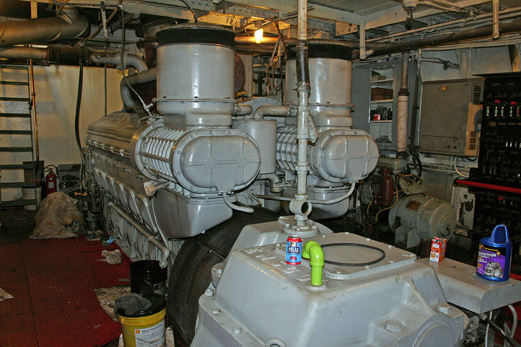
McAllister would repower the tug with a WWII surplus LST package – a 900HP EMD 12-567ATLP, with a Falk (Falk designed, however several contractors during the war built them, including Esco and Lufkin) reverse-reduction gear. This was one of the most common tug repower packages used after WWII, and I am slowly working on a large post about them.
The engine in the Pegasus was originally installed in Landing Ship Tank (LST) #121, shipped by EMD 6/16/1943. LST 121 was launched August 16, 1943 by Jefferson Boat & Machine. 121 would spend her career on the Pacific front and was present at the Marshall Islands, Iwo Jima, The Marianas, Western Caroline Islands and the Tinian Capture, earning 5 battle stars. She would be sold for scrap in 1946.
The Pegasus project fell dormant, and was looking for new caretakers and leadership for several years. Unfortunately, nothing would come to fruition. The museum ship world is one of the hardest aspects of preservation out there, and it gets harder every year as these boats get older. We have lost numerous preserved tugs just in the last few years. Times are tough, but be sure to help support your favorite museum ship. Every one of these groups needs all the help they can get.
This week’s column is by Jay Boggess. Next week we will return to the Delta Municipal Power Plant for Part II.
Pretty quickly, early on – when it comes to diesel engines, you hear the word “Roots Blower”. But who IS Roots? Today in the era of Wikipedia, this is an easy question to answer, but not when I was a kid.
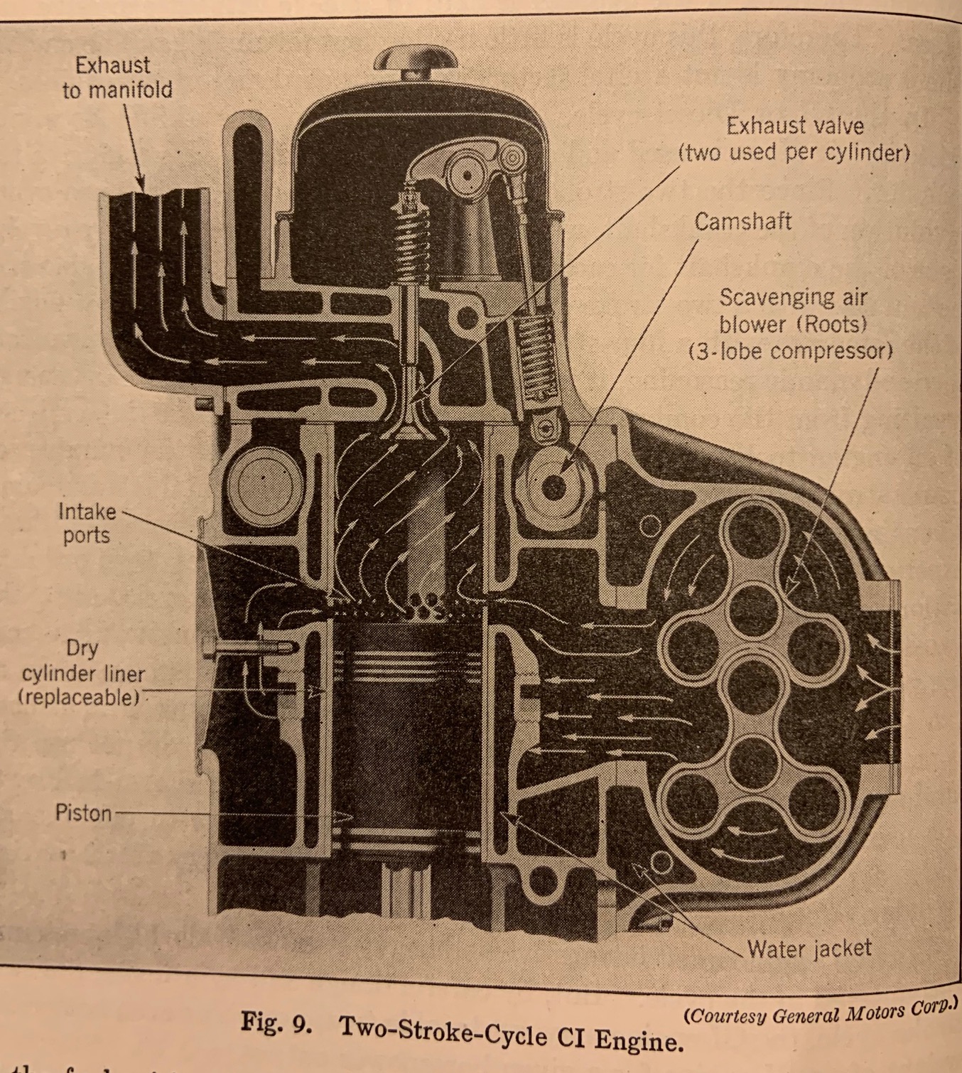
I’d first heard of the “GMC Roots Blower” associated with supercharged dragsters & hot rods. Later, while reading my father’s 1944 textbook “Internal Combustion Engines – Analysis & Practice”, I discovered a cutaway section of the General Motors 2-stoke CI (compression ignition or diesel) engine, below:
Later, I learned that Cleveland Diesel, Fairbanks-Morse and Electro Motive Division diesel engines all had Roots Blowers, but no one ever explained why it was called the Roots Blower.
In 2003, a random visit to the History Colorado Museum in Denver came across this artifact:
Click for larger – History Colorado Museum – Jay Boggess photo – 2003
A mine ventilation blower for ventilating underground hard-rock mines, built by the P.H. & F.M. Roots Company, Connersville, Indiana. The placard listed a date, but the low-res digital pics of the era do not allow me to zoom in – other sources point to the mid 1880’s or so.
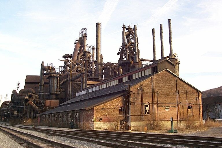
Another datapoint came from another random visit, this time to the nearly preserved Bethlehem Steel blast furnaces in Bethlehem, PA (thanks to my former EMD colleague Mark Duve, who insisted we stop).
Click for larger – Bethlehem Steel blast furnaces – Bethlehem, PA 2004 – Jay Boggess photo
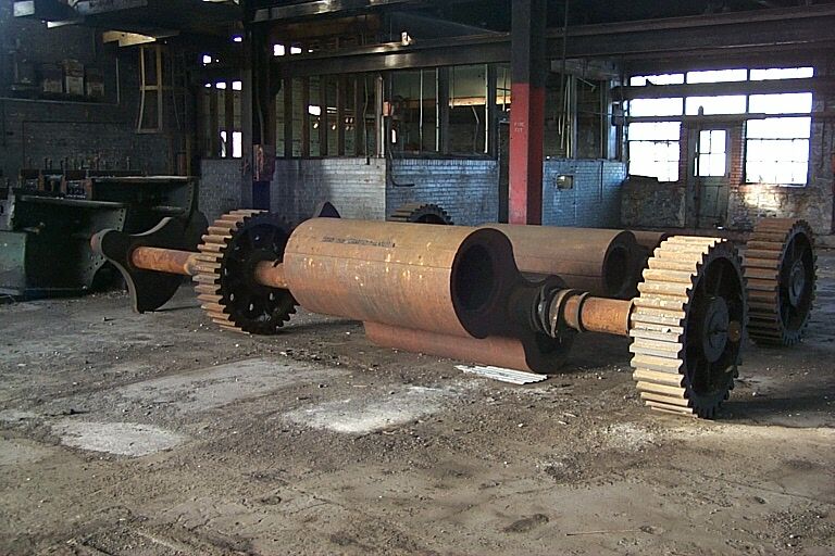
The building in the foreground of the photo was unlocked, we ventured inside and discovered these:
Bethlehem Steel blast furnace blower rotors – Bethlehem, PA 2004 – Jay Boggess photo
Very distinctive, two-lobed Roots Blower rotors – look carefully and you will see counter-weighted steam engine eccentrics on the end of the rotors. Inside the same building were the matching horizontal steam engine cylinders for driving these rotors (I took photos but the passage of 16 years has lost those). I later learned that blast furnace blast supply was one of the first uses of Roots Blowers.
So who were P.H. & F.M. Roots? Wikipedia points to a 1931 book, “Indiana One Hundred And Fifty Years of American Development” which provides most of the answers. Philander Higley and Francis Marion Roots were brothers. Francis was the youngest brother, born in 1824, went searching for gold in California in 1849, came home in 1850 and started working with his brother Philander in manufacturing. They patented the “Roots Positive Blast Blower” in 1866. Francis passed away in 1889, Philander passed in 1879. Their company was purchased by Dresser Industries in 1931, and renamed the Roots-Connersville Blower Company. In WWII, they produced low-pressure blowers for blowing ballast tanks in U.S. Submarines, as well as centrifugal blowers for various low-pressure/ high-volume uses, eventually submerged in the vast Dresser product line.
Roots Blower Applications:
Submarine Ballast Tank Blower:
Click for larger – collection of the Bowfin Museum, Pearl Harbor, HI – Jay Boggess photo
Roots blower on USS Bowfin, Pearl Harbor, HI – Jay Boggess photo
This is listed on the drawing as a 1600 CFM blower, designed and built by the Roots-Connersville Blower Corporation, Connersville, Indiana. The driving motor is a 1750 RPM, 90 horsepower, intermittent-duty DC motor.
To digress extensively – WWII submarines had two systems to blow their ballast tanks – 3000-PSI stored compressed air reduced down to 600 PSI to start the surfacing process and 10-PSI low pressure air supplied by blowers to finish the job once a submarine surfaced. It was this low-pressure job that either Roots Blowers or centrifugal blowers were utilized. Another interesting use was that when a sub is submerged, various tanks are vented inboard the sub, raising the internal pressure of the boat several PSI above atmospheric pressure. If the hatch were immediately opened, the rush of air was known to launch sailors overboard. Instead, the hatch between the conning tower and control room would be shut, the boat surfaced and the bridge hatch opened. While the captain checked to see if the coast was clear, the low-pressure blower is started finishing the blow of the ballast tanks and reducing the excess air pressure inside the rest of the boat.
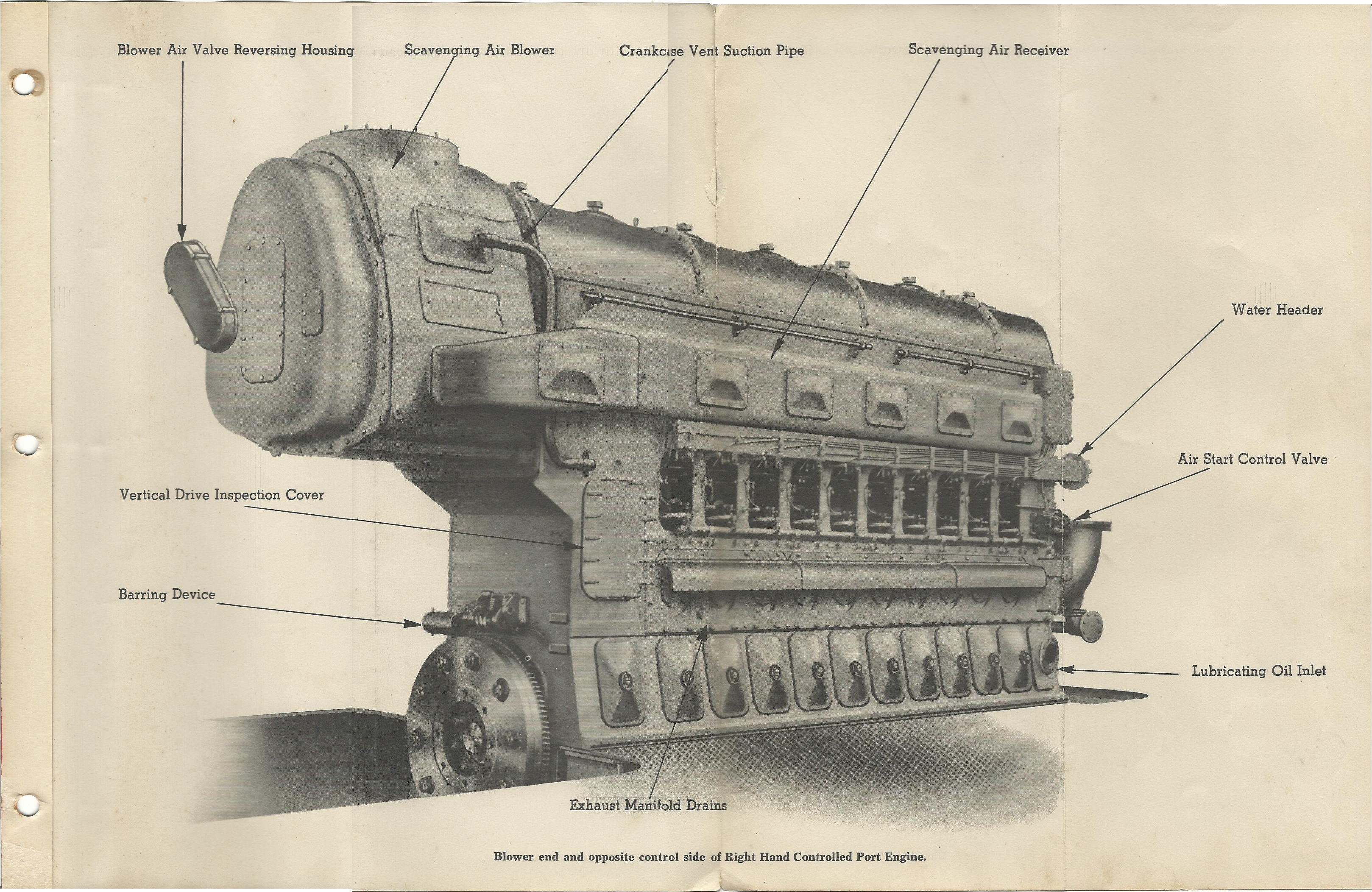
Fairbanks-Morse Opposed Piston 38D Engine:
Click for larger – From the Fairbanks-Morse LSM 38D 8 1/8 Manual – collection of Paul Strubeck
The WWII era FM 38D manual does not use the word “Roots Blower” but instead refers to it as a “Scavenging Air Blower”. The FM 38D blower spins at 1450 rpm and provides 6000 CFM at about 2 to 4 PSI. The Direct Reversing version of this engine used a set of linkage and air valves on the blower in order to direct the air in the proper direction when the engine is running astern, thus the blower is running backwards.
General Motors Cleveland Diesel Engine Division (CDED) 278A Marine Diesel:
Cleveland Diesel Engine Division Diagrams – Click for larger
Click for larger – Cleveland Diesel Engine Division Photo – Collection of Jay Boggess
Cleveland Diesel mounted their single Roots Blower on the front of their engine, essentially shortening or lengthening the blower to fit the air flow of the 6, 8, 12- or 16-cylinder models of the 278A, as the photos and following table illustrates.
Cleveland Diesel Engine Division Photo – Collection of Scott D. Zelinka
Cleveland Diesel Engine Division Photo – Collection of Scott D. Zelinka
Thanks to Scott Zelinka for the above Cleveland photos showing a pair of the Spiral rotors used by CDED. The clearances between the rotors is set at .024″ (on the 12 and 16 Cyl) and .018″ on the smaller engines. I find it downright amazing that something with this complex of a shape – and interlocking none the less, could be machined so exacting by hand, and mass produced at that, long before computers and CNC.
With the new Cleveland Diesel 498 engine, a small Roots blower was used in conjunction with the exhaust driven turbocharger to provide for lower RPM scavenging. EMD would solve this issue with their own turbocharger on the 567. A centrifugal clutch drives the blower off of the timing gears that would disengage at a certain RPM and allow the turbocharger to freewheel.
Cleveland 498 diagram
Click for larger – The blower is in the same location as the 278A series, behind the intercooler here.
EMD 567/645 Roots Blown Engines
Electro-Motive answered the Roots Blower question in a totally different way than its GM sister division CDED. EMD also had four different engines to support: 6 – 8 – 12 – 16 cylinders. EMD picked one design of blower, then used that one blower for the 6 and 8 cylinders model and a pair of blowers for the 12 and 16 cylinders, changing the blower gear ratio (and blower RPM) between 6 and 8, and 12 and 16 engines, gaining economics of scale and fewer replacement parts to support.
Below is the 8-cylinder 567 model:
Click for larger – Cleveland Diesel engine manual photo – WWII Army ST tug – collection of Jay Boggess
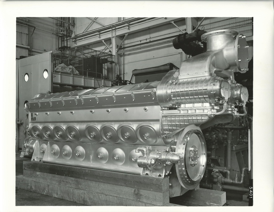
And here is the mid-1950’s 16-567C model. Note the directional air intake, a sign that this engine was likely built for stationary power generation.
Click for larger – Cleveland Diesel Engine Division Photo – Jay Boggess Collection
The 16-567C pic illustrates another clever design feature that EMD incorporated. By placing the Roots Blowers high above the crankshaft (driven by the engine’s camshaft drives), EMD designers provided a niche for a generator underneath the blowers, saving overall length of the engine/generator and thus overall length of the locomotive.
These are just a few short uses of the Roots Blower – several other manufacturers have used them, and coming in one of the next parts on the Delta Municipal Power Plant, we will see a giant Roots-Connersville centrifugal blower used to feed the big 31A18 engine. Roots Blowers are common on many different industrial uses outside of engines.
While many thousands of Roots Blowers have been built, I believe their day in the sun has passed. From my days at the Alaska Railroad, EPA emissions regulations were starting to close in on the Roots Blown engine. I do not know the specifics, but the GP38-2s AkRR owned had to be de-tuned for better emissions, which gave lower fuel economy. And even then, the EPA wasn’t very happy about it (that is, the EPA Tier 0/1/2/3 regulations only allowed de-tuning for existing engines and would not be applicable to a new Roots-blown EMD engine).
So, when you hear an older EMD go by, be it a GP7 or GP9 or 38, think of Philander Higley and Francis Marion Roots and what they invented 150 years ago.
Sidebar – Roots Blower Or Roots Supercharger?
Blogmaster Paul Strubeck has uncovered somewhat heated discussions between the terms “Roots Blower” and “Roots Supercharger”. Both terms can be correct – I will attempt to clarify, but I will preface my comments that I am an electrical engineer by training / experience and only an “armchair” engine guy (from hanging around my father and the many, many gear-heads at Electro-Motive over 22 years).
Supercharging is defined as jamming more air than atmospheric pressure into each cylinder before compression by the piston begins. My 1944 internal combustion textbook notes by providing some form of air pump, you can get more power for the same engine weight or thin-air compensation for an aircraft engine at high altitude.
In the two-cycle diesel engines (FM, Detroit Diesel, CDED, EMD), the Roots Blower acts primarily to scavenge exhaust gases from the cylinder after each power stroke. If the exhaust valves close before intake ports (in the case of a GM 2-cycle diesel), then some supercharging will take place. But the primary purpose is to get exhaust gases out.
If the air pump is driven by a turbine attached to the exhaust manifold, then the arrangement is termed a turbocharger. The turbocharged EMD 645E3 engine provides 3000 THP in the GP40/SD40, while the Roots-blown 645E engine of the GP38 provides only 2000 THP. The Wright radial engine of the Boeing B-17 of WWII used a turbo-supercharger so that it could fly at 25,000 feet over Germany, with each engine producing 750 HP at altitude.
Barney Navarro was the first hot rodder to put a Roots Blower with Detroit Diesel history on a car engine in the 1950’s. The blower, from a Detroit Diesel 3-71 was belt driven off of the crankshaft and made 16PSI of boost in the engine. After that the doors opened and the Roots style blower became a choice power added for race cars (typically drag cars). Today, they are still referred to an x-71 style (in different sizes, including a 14-71, an engine never made), however they are specific made for the application, and not WWII surplus! Supercharging on gasoline/car engines is a much larger topic that literally has had books written on it.
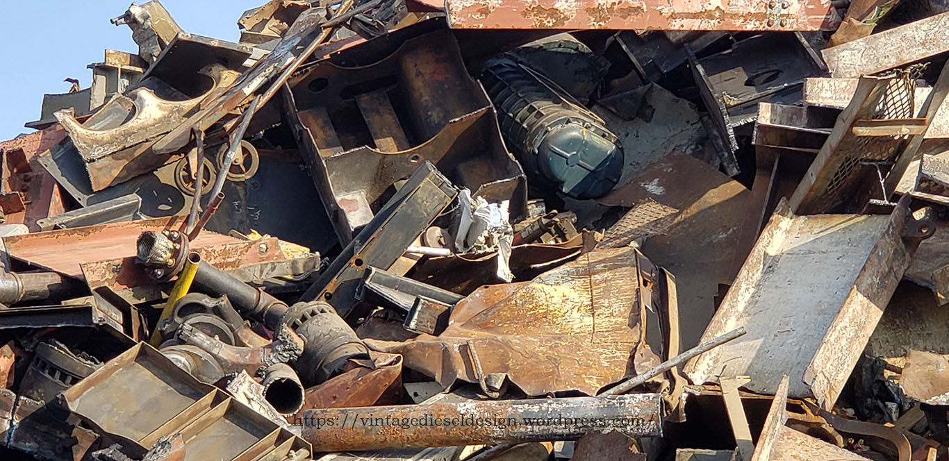
As I suspected, it took about 25 seconds before it was figured out what it was. Yup, Its an EMD 567C or some flavor of 645. Unfortunately, I know nothing of the story as to why this engine was in a Brooklyn junk yard in July of 2019..but, makes for an interesting conversation none the less. Its not often you see a Teal painted engine, so I am kind of assuming it was some sort of stationary application that got scrapped out. Here is some more photos, click them all for larger views.
On the top Left is part of the crankcase/airbox, top Right is a blower with a chunk of crankcase next to it, below that is a liner and the crankshaft, and on the bottom Left is some more crankcase chunks.
Closer view.. The pile was shuffled around the following day.
Better view of the crank and a liner.
A pair of power assembly’s still in the block, torched into bite sized pieces.