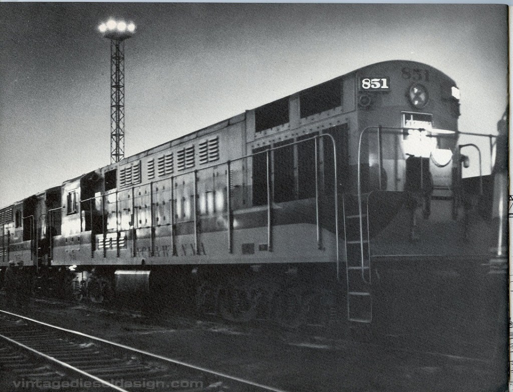
A few years ago, our local bookstore took in a large collection of railroad books. In rummaging, I stumbled upon an old Fairbanks-Morse promotional booklet promoting the Delaware Lackawanna & Western’s new FM H-24-66 Train Master locomotives, which were at that time the highest horsepower locomotives being offered. DL&W being a favorite railroad, of course I needed it!
So, I take the booklet up to the counter being it had no price on it.. and I inquire. “Oh, that’s..old, were gonna need to research this..”. In other words, you want a lot for it. I go back a few months later and sure enough, they wanted north of $200. Nope, not for a little 20 page promotional booklet!
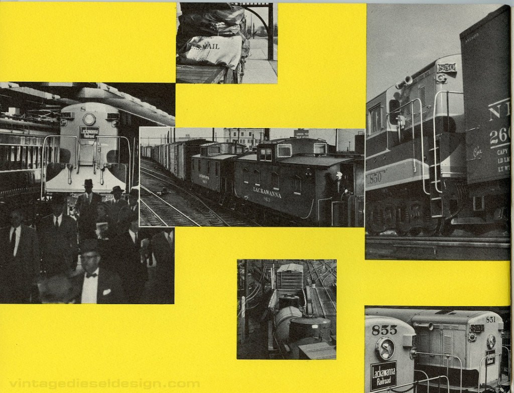
Fast forward about 2 years ago I stumbled on a cheap copy on eBay, and wound up winning it for only like $25! So, here is a scan of “The Lackawanna Story”.
Said bookstore still has their copy of it, down to only $175 now!
Yeah, when I first head about that, I scratched my head also.
We are all familiar with the Fairbanks Morse 38D opposed piston engine. The engine has its roots back to 1933 with a 6-cylinder design. It used a very boxy, cast iron block, with a small 5″ bore and 6″ stroke, hence the 38A5 model designation. The odd thing about this engine, is that it used a chain driven upper crankshaft!
Check out the original patent for this engine, filed by Heinrich Schneider and Percy Brooks on behalf of Fairbanks Morse in September of 1933.
By 1938, a new welded frame was introduced, and gave the OP the appearance we all know of today, however, that upper crankshaft was still chain driven.
The engine, with a 5″ bore and 6″ stroke was first used in a doodlebug railcar for the Milwaukee Road. At the same time, a larger 8″ bore engine was introduced. The engines were a success, and would catch the eye of the US Navy.
I was recently able to purchase a manual, which best I can tell is from 1937, for the Fairbanks Morse 38C5 engine, the slightly newer version of that prototype mentioned above. While the manual is extremely primitive, it does illustrate that chain driven upper crankshaft assembly. A second chain was used for the camshafts and timing.
According to C.H, Wendel in his 100 Years of FM Engine Technology book, the chain would be replaced in 1937 with a vertical drive shaft operating off of bevel gears on each crankshaft, which is still used to this day, however that second timing chain is still in place. The engine would go through a multitude of improvements, in which the engine reached its two main production sizes, the smaller 5 1/4″ x 7 1/4″ introduced in 1939 and the 8 1/8″ x 10″ in 1938. The larger of the two still being produced, with the smaller being discontinued in the early 1970’s. A full post on the smaller engine is planned.
While Diesel engines were in their infancy with design work changing daily, I still look a this and go “What were they thinking!?”
Amazingly enough, a pair of those original FM 38A5 engines still exist, from the USS Enterprise (CV-6). The engines were saved by the Rock River Thresheree, north of Beloit, WI.
June is a the two year anniversary of this blog, and with that I am kicking off a series dedicated to the Cleveland 498 engine. The 498 engine has been shrouded in mystery over the years, and was one of the main driving forces of creating this page. I wanted to do a writeup on the engine, but had no place to put it! Just to put this right on top – if anybody has any stories, recollections, information, photos or documentation on these engines, PLEASE send me a message! I am trying to document these engines as best as I possibly can.
In the days after WWII, medium speed, 2-stroke diesel engines essentially hit a horsepower wall, around 1600HP or so. A common way or obtaining a higher horsepower rating, was simply to add more engines! Unfortunately, adding more engines, means more space is being taken up. So, the solution is to try and get more horsepower out of what you already have.
Enter turbocharging.
Now, turbocharging was not a new concept by any means. Many diesel engines benefited by use of turbocharging, but these were almost all 4-stroke engines. Cleveland Diesel had a single turbocharged 4-stroke engine design during WWII, the 258S (originally a Winton engine) which was a 2000HP direct reversing engine built for subchasers. Even several WWII aircraft, including the B17 Bomber were turbocharged. Turbocharging a 2-stroke engine was an entirely new concept. As it is, a 2-stroke requires some form of positive displacement blower for scavenging. The issue with adding a lone exhaust-driven turbocharger, is in periods of startup, lower idle and acceleration, the engine gets starved for air, as it is not providing enough exhaust to spin the compressor. Kind of a catch 22 situation. More on this later.
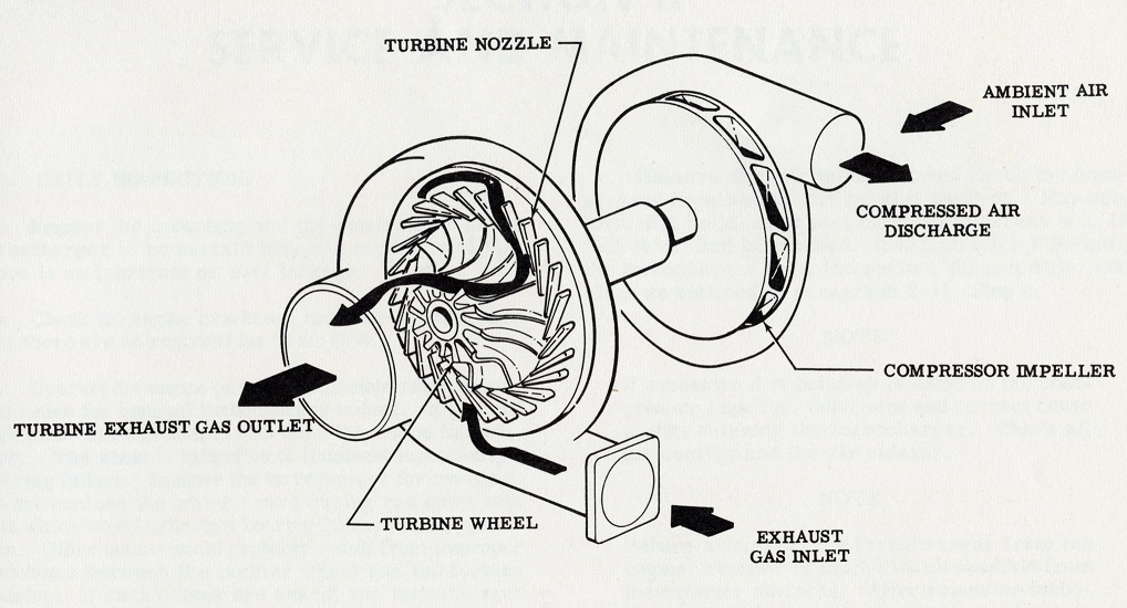
The basic operation of a turbocharger from a Garrett-AiResearch manual.
Throughout WWII, General Motors Diesel (Cleveland Diesel, Detroit Diesel & Electro-Motive) was the leading Diesel engine supplier to the war effort. Cleveland Diesel would supply over 13,600 engines (from 7-1939 thru Dec 31, 1945), be sure to read our history about Cleveland Diesel here: Cleveland Diesel Engine Division – GM’s war hero turned ugly stepsister
The Cleveland 16-278A engine was one of the most widely used engines during the war and peaked at about 1800HP, which was about on par with the EMD 16-567C, which was introduced in 1953. Alco was already there with their 12-251B, also making 1800HP, however this was a 4-stroke, with a turbocharger already. Fairbanks-Morse cracked the magic 2000HP barrier in a medium speed engine with the 10-cylinder 38D OP engine by 1950, using only a Roots style blower.
With General Motors (and Cleveland Diesel) still working closely with the Navy, an experimental test was devised by the Navy’s Engineering Experiment Laboratory in Annapolis, Maryland in 1947 to start testing turbochargers. A proof of concept test was launched, using a Detroit Diesel 1-71 (yes, GM turbocharging has its roots in the diminutive, little 1-71 engine!). With the proof of concept done, more testing was devised in the early 1950’s at the Engineering Lab using a bone stock 16-278A engine. A test was devised in which a mock “turbocharger” (another Roots blower) was installed on the test floor, operated by an electric motor, to feed the engine in a simulated and controllable environment. A goal was set to maintain a cylinder firing pressure in the area of 1300 PSI (compared to the stock 850-1050 PSI) and make 3,000HP. Numerous tests were conducted with various configurations of inner and after coolers, blower sizes, injectors, controlling exhaust timing and use of snorkels for Submarine use. A similar test was conducted using an 8-268A engine as well. Unfortunately, I have yet to come across any photos of these tests.
The winner – Using the stock configured 16-278A engine, with turbocharger feeding the Roots blower with an aftercooler made an impressive 2,990HP at its rated 750RPM. With controlling the exhaust timing, the engine made 3,130HP. Amazing numbers for a stock engine! Not to mention, a true testament to the engineering of this engine, and its ability to take such punishment.
Performance ratings for the test engine, from Turbo-charged engines for the Navy, by L. Wechsler and T.W. Shipp, Internal Combustion Engines Branch, Bureau of Ships
After the tests, three turbocharger manufacturers would begin working with the Navy to spec out an appropriate design, and how to supply the air to it, be it via individual ducts from each cylinder (common on 4-strokes), divided manifolds or a single manifold using a venturi system. The results of the testing were concluded in a presentation at the SAE National Diesel Engine Meeting on October 27th, 1954. The report, High Supercharging, Development of a GM 16-278A 2-Stroke-Cycle Diesel Engine, was presented by Warren G. Payne and Wolfgang S. Lang of the US Naval Engineering Experiment Station.
Unfortunately, not all the testing was complete at the time of this paper, so it is unknown just how well the testing progressed when the turbochargers were installed on the engine. What is known, is that testing further proceeded at the Engineering lab on the 16-278A, The Lanova Corporation handled the 6-71 testing in New York, and De Laval Steam Turbine further tested the 8-268A at their own lab.
The test 8-268A test engine at the De Laval test lab, used a model B-8 turbocharger. From a 1955 De Laval advertisement.
After the presentation, a discussion panel ensued, which is also part of the transcript of the report, in which comments were heard from other engine builders and engineers. One such stands out: Rudolph Birman of the De Laval Steam Turbine Co., who essentially picked apart the findings. Mr. Birman states several things, such as:
“Water cooling of the exhaust manifold cannot be tolerated in a turbocharged 2-stroke engine.”
“All starting, idling and high exhaust back pressure problems are eliminated, however, if the positive displacement blower is retained and the turbocharger arranged to operate in series therewith.”
“There is a similar disagreement between the findings of the authors and those of De Laval with regard to the location of the intercooler in a turbocharger-positive-displacement-blower in series arrangement.”
I do not know if De Laval were working behind the scenes with GM/Cleveland Diesel already (given the time frame, they must have been), however, Mr. Birman’s commentary would essentially be the entire basis for what would become the 498 engines in just a few short years.
The concept drawing of the Cleveland 498 first appeared in the August 1955 issue of Diesel Times, along with some basic specifications and features.
Another set of comments worth noting, was from A.K. Antonsen and E.L. Dahlund of Fairbanks, Morse & Co. FM was working in-house on their own turbocharger design, starting in 1945 on a basic 10-cylinder 38D 8 1/8th OP engine used in submarines, as well as a smaller 3-cylinder 5¼” OP engine. Full production of a turbocharged OP engine was not offered commercially until sometime in the late 1950’s (Anybody have a specific year?). The Turbo OP would be a very popular stationary power engine, and would peak at over 4,400HP for the 12-cylinder engine.
FM’s Turbocharged OP engine is still produced today, producing astronomical amounts of horsepower mainly for standby power generation. Note that like the Clevelands, it retains the Roots blower. FM Brochure
As mentioned above, one of the shortcomings of the turbocharger on a 2-stroke is the lack of enough scavenging air. The issue was addressed by simply retaining the Roots blower, but it was found a smaller one would work (we will get to this more in Part II). With the testing on the 268A engine, in place of the blower a small hydraulic motor was tested mounted to the turbocharger. In periods of low RPM, the hydraulic motor would turn the compressor, essentially making artificial air pressure with the turbo. The pump for the hydraulic motor was driven by the engine.
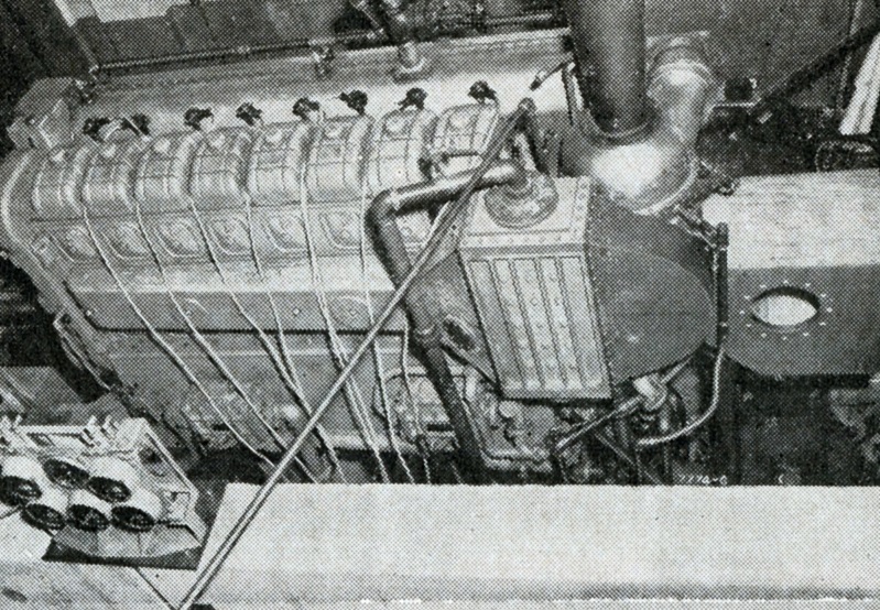
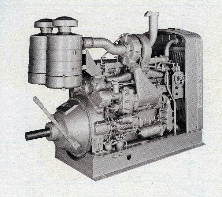
An early Detroit Diesel 6-71T engine used for an industrial application.
With Cleveland Diesel now working on a whole new turbocharged engine – GM sister division Electro-Motive was doing the same. EMD started their own program in January of 1955 to turbocharge their current 567C engine, unlike Cleveland, they did not start by redesigning the entire engine from the ground up. Like the Navy tests, EMD used an electrically-driven Roots blower in a mock test using a 12-567C engine for development purposes, but EMD would design their own turbocharger for the 567C engine. Instead of using the combination Roots blower and turbo in series, EMD designed their own all new turbocharger, which would be mechanically-driven from the camshaft through a geartrain during starting, low speed, low power and accelerations, providing scavenging air. The turbocharger is connected to the geartrain through an overrunning clutch. At certain power levels (approximately Throttle Position 6 on a locomotive), there is enough energy in the exhaust so that the turbo runs faster than the geartrain, the overrunning clutch disengages, providing “free” turbo-supercharging. This would go on to become a very successful design and used throughout the 710 line (with several refinements of course). EMD’s first production turbocharged locomotive, the 2400HP SD24, was introduced in 1958. We may do an article specific to EMD turbocharger history down the road, but for now we will stick to the CDED 498.
The prototype turbocharged EMD 16-567C engine from “Performance of a Turbocharged 567C engine” by A.N. Addie/EMD. Production turbochargers would be used only on 16 cylinder engines, and were given the “D” model. Turbochargers would not be used on 12-cylinder engines until the 645 line.
Union Pacific Railroad was doing their own separate development with adding turbochargers to the 567C used in GP9 locomotives starting in 1955. Working with Garrett-AiResearch – (later makers of the turbocharger used on the 6-71), a manifold was devised, and four small turbochargers were added feeding into the stock Roots blowers through an intercooler. UP would also test engines with turbochargers made by Elliot, but using only two slightly larger ones then the Garrett installation. These tests were successful, and several engines were converted. UP would send GP9’s to EMD in 1959, which were upgraded with new EMD turbochargers for further testing. Ultimately these test engines were converted to EMD turbochargers, or had them removed. I urge everyone to read Don Strack’s Utah Rails page on the Omaha GP20’s for much further information on this test program. Please be sure to visit the links below.
The quad Garrett turbochargers installed on the 567C. Note the complex plumbing for the exhaust and charge air going to the blowers. Union Pacific Photo, Don Strack Collection.
The Elliot installation was a little more simplistic, with a single exhaust manifold feeding a pair of slightly larger turbochargers, with each one feeding one of the blowers. Union Pacific Photo, Don Strack Collection.
The Cleveland 498 made its public debut at the General Motors Powerama Festival. Powerama was held August 31st-September 25th of 1955 in Chicago, Illinois. The event, “A Worlds Fair of Power”, would be a giant showcase of products from General Motors, including Cleveland Diesel, Electro-Motive, Detroit Diesel, Euclid, Allison, GMC Truck & Coach, Fabricast and Frigidaire. On display were numerous engines, pieces of heavy equipment, locomotives, and even the Great Lakes Towing tugboat Laurence C. Turner, and the Fleet Submarine TautugSS-199.
The first Cleveland 498 displayed at Powerama. I have my doubts that this was a full production engine, as it just does not look “right”, especially the exhaust jumpers and manifold. I think this was more of a mock up model for display. Note the differences just in the cutaway model on the left. The first production engine used commercially was still several months out. Unknown photographer, VDD collection.
Stay tuned for Part II, where we will discuss the 498’s design features and specifications.
Engine #7 at Delta is a 10 cylinder, 3500HP, Dual Fuel engine. The engine is rated for only 277 RPM, and has an 18″ bore and a 27″ stroke.
Click on all of the photos for a larger version.
The creative use of old stop signs are covering the exhaust ports, which would turn and enter into the flood in the circular covers.
One of the fuel injection pumps. A camshaft in the box underneath drives these, with a copper line out of the top leading to the fuel injection nozzle in the head.
The engine drive a Fairbanks-Morse 2130kW, 2400V AC Alternator. The excitation generator is belt driven off off the end.
Looking down at the top of the cylinder head. The large pipe leading into the top of the head is the incoming Natural Gas supply. Going clockwise, is the gas admission valve driven from the upper camshaft, the air start check valve, with the air supply under it, jacket water exit into the upper water header, above that is the cylinder relief valve. In the center is the fuel injection nozzle. According to the builders plate, this engine is a 31A18 – FM documentation calls the Dual Fuel engine a 31AD18, maybe this engine was converted after installation?
The pipes in the foreground are the previously mentioned exhaust pipes, which were removed for remediation.
Just outside of the engine hall, is a small clean air room. Inside, is the scavenging air blower for the engine (all 10 cylinder engines used an external blower) – a Roots-Connersville 24″ centrifugal blower. The blower, is rated at a whopping 300HP and moves 17,500CFM of air.
Just how big is an 18″ piston? Here it is with a dollar bill for reference..
Gauge and alarm panel – Just not as cool as those 1930’s era ones on the 32E engines..
The photos here simply do not do this engine justice, and just how BIG it is!
Lubrication chart for the engine. I would LOVE to add one of these to my collection. Anyone got one they want to sell?
This concludes our tour of the Delta Municipal Light & Power Plant. Thanks again to the guys for the fantastic tour! I can only hope that this plant can be saved, or at least some of the engines. I would love to see the 31A18 saved, but realize that would be one hell of a feat, due to the shear size. That little 4 cylinder 33 would be a neat museum piece as well.. I may make another post down the road with some other random photos in the plant I took.
Next week starts a new series – Historic Boat Profiles, with our first featured boat being the tug M. Moran, Moran Towing’s first twin screw tug.
I am way behind in posts as usual, so here we are continuing with the Delta series, this week highlighting the 32E engines, the original engines at the plant.
Moving down the line of engines we get to engines #3, 4 and 5, all of which are Fairbanks-Morse 32E14 engines. The 32E was a descendent of the model Y engine, first introduced in 1923, and subsequently went through several upgrades over the years. The engine, offered in two sizes: A 12″x15″ and a 14″x17″. The engines were identical, other then the bore and stroke, with the 12″ offered in 1, 2 and 3 cylinder models, and the larger 14″ in 1, 2, 3, 4, 5 and 6 cylinder options. The 32E engine is a 2 stroke Diesel, and used a unique backflow scavenging, in which on the up stroke of the piston, air is pulled into the crankcase through a simple air valve on the crankcase door, is compressed on the downstroke, and when the piston uncovers the exhaust and intake ports on the liner, the compressed air forces the exhaust out, a very simple and effective method, requiring no camshaft operated valves in the cylinder head. An oil pump kept a force feed lubricator full, which handled the oiling on the cylinder walls, wrist pins and crank pins, as well as keeping a certain oil level maintained at each of the main bearings using a series of drilled passageways. The engine had no water pump of its own, relying on an external pump in the plant. A plunger type fuel pump was operated by a camshaft on the governor drive. The engines originally used a very basic FM flyweight style governor, and later used a Woodward IC unit. The 32 line would become one of the most popular engines of its time, powering numerous rural communities and small business (be it power generation or through a line shaft).
Click on all photos below for a larger version.
Engine #4 is a 300HP engine at only 300RPM, driving a 148kW alternator.
The 32E engine commonly used a very basic exhaust system, where each cylinder simple exhaust into a downward pipe, that tie into a chamber under the floor that runs outside to the muffler.
Engines #4 and 5 are smaller 3 cylinder, 225HP engines. Unfortunately, I did not get the size of the alternators that they drive.
The pipe above the exhaust manifolds is the upper water header. These are extremely basic engines, and while today are tiny in terms of ratings, several are still in service all around the country, not only in their original plants, but many preserved at old engine clubs.
Looking down on the cylinder head, we see the fuel injection nozzle in the center, as well as the jacket water exit.
Behind each alternator, the same shaft also turns the excitation generator.
Next week will be the final part of the Delta series, covering the biggest engine in the plant, the 31A18. After that we will start a new series, Historic Boat Profiles, as well as returning to vintage advertising and some great articles which have been in the works for several months behind the scenes.
The Delta plant is home to a trio of F-M model 33 engines. Before we get to those, here is a little background on the Model 33 engine.
The Model 33 engine was the next model in line after the 32 series, and was introduced around 1930. The engine was ultimately offered in 3 bore sizes – a 12″, 14″ and 16″. The engine was FM’s first pump scavenged engine, moving up from the older crankcase scavenged 32. Like the predecessor, these were rather simple engines. No intake or exhaust valves, mechanical fuel injection (in a time when air injection was still somewhat common) and a split lubrication system using both an engine driven pressure pump and a force feed mechanical lubricator.
In the case of this post, we will be describing the 16″ bore model, which has a 20″ stroke rated at 300RPM. FM offered these engines in 4, 5, 6, 7, 8 and 10 cylinder sizes. The engine was available with a dual fuel option, meaning it could run on Diesel, or Natural Gas with Diesel acting as a pilot fuel. A second upper camshaft drives a series of gas valves at each cylinder head. The Delta plant has 3 of these engines:
Unfortunately I did not ask as to the chronological history as to just when these engines were installed.
Lets start at Engine #1 – Click on images for larger versions
Looking at #1, we see the main exhaust leading into the floor, where it then heads outside into the muffler. Mounted on the side of the scavenging pump is the lube oil heat exchanger, as well as a set of oil strainers.
On the side of the engine is the starting hand wheel, fuel injection pumps, and the Woodward governor.
On the left side is the Natural Gas header pipe, with the starting air pipe being the other large pipe going into the head. In the center is the fuel injection nozzle.
A look at the cylinder head cross section.
Top of the scavenging pump.
Control side of the engine. I honestly do not know what the additional box is between the scavenging pump and the intake belt is, but I do believe it is an intercooler of sort. I have not seen this on any other FM engine, and I did not notice it to ask when I was there. I imagine it has to do with emissions.
The engine drives an 835kW AC Alternator. F-M supplied all of the electrical gear to the plant as well.
Straight on side view of the engine. This engine in marine form was known as the model 37F16, a direct reversible engine common to tugboats in the 1950’s. A final look at Engine #1.
Engine #2
Engine #2 is a small, 4 cylinder 33D16 engine. F-M would upgrade the letter designation as the engines advanced through the years, thus this is the older of the trio, being a “D” engine.
Other then being short 2 cylinders, the engine is exactly the same as #1 above.
What is interesting is the additional plates between the cylinder heads. I have never seen these on a marine engine.
While I thought I thought I got photos of everything, I missed getting a photo of several data plates, thus I do not know how large the Alternator is that this engine drives.
Engine # 6
Engine #6 at Delta is the 2nd largest engine of the plant, rated at 2,000HP.
Notice anything missing? No scavenging pump! The 10 cylinder model utilized a motor driven centrifugal blower, mounted externally. We will discuss these more when we get to the 31A18.On the front of the engine is the main lube oil pump. Again, standard controls like the previous engines. Note that this one is the opposite rotation though. The gauge board. Note the feed lines coming up from the floor. The exhaust side of the engine. Note the large grey pipe in the background – this is the scavenging air intake. This engine drives a 1200kW alternator, at 60 cycles.
In the next part we will go over the trio of 32E14 engines at the plant.
This week’s column is by Jay Boggess. Next week we will return to the Delta Municipal Power Plant for Part II.
Pretty quickly, early on – when it comes to diesel engines, you hear the word “Roots Blower”. But who IS Roots? Today in the era of Wikipedia, this is an easy question to answer, but not when I was a kid.
I’d first heard of the “GMC Roots Blower” associated with supercharged dragsters & hot rods. Later, while reading my father’s 1944 textbook “Internal Combustion Engines – Analysis & Practice”, I discovered a cutaway section of the General Motors 2-stoke CI (compression ignition or diesel) engine, below:
Later, I learned that Cleveland Diesel, Fairbanks-Morse and Electro Motive Division diesel engines all had Roots Blowers, but no one ever explained why it was called the Roots Blower.
In 2003, a random visit to the History Colorado Museum in Denver came across this artifact:
Click for larger – History Colorado Museum – Jay Boggess photo – 2003
A mine ventilation blower for ventilating underground hard-rock mines, built by the P.H. & F.M. Roots Company, Connersville, Indiana. The placard listed a date, but the low-res digital pics of the era do not allow me to zoom in – other sources point to the mid 1880’s or so.
Another datapoint came from another random visit, this time to the nearly preserved Bethlehem Steel blast furnaces in Bethlehem, PA (thanks to my former EMD colleague Mark Duve, who insisted we stop).
Click for larger – Bethlehem Steel blast furnaces – Bethlehem, PA 2004 – Jay Boggess photo
The building in the foreground of the photo was unlocked, we ventured inside and discovered these:
Bethlehem Steel blast furnace blower rotors – Bethlehem, PA 2004 – Jay Boggess photo
Very distinctive, two-lobed Roots Blower rotors – look carefully and you will see counter-weighted steam engine eccentrics on the end of the rotors. Inside the same building were the matching horizontal steam engine cylinders for driving these rotors (I took photos but the passage of 16 years has lost those). I later learned that blast furnace blast supply was one of the first uses of Roots Blowers.
So who were P.H. & F.M. Roots? Wikipedia points to a 1931 book, “Indiana One Hundred And Fifty Years of American Development” which provides most of the answers. Philander Higley and Francis Marion Roots were brothers. Francis was the youngest brother, born in 1824, went searching for gold in California in 1849, came home in 1850 and started working with his brother Philander in manufacturing. They patented the “Roots Positive Blast Blower” in 1866. Francis passed away in 1889, Philander passed in 1879. Their company was purchased by Dresser Industries in 1931, and renamed the Roots-Connersville Blower Company. In WWII, they produced low-pressure blowers for blowing ballast tanks in U.S. Submarines, as well as centrifugal blowers for various low-pressure/ high-volume uses, eventually submerged in the vast Dresser product line.
Roots Blower Applications:
Submarine Ballast Tank Blower:
Click for larger – collection of the Bowfin Museum, Pearl Harbor, HI – Jay Boggess photo
Roots blower on USS Bowfin, Pearl Harbor, HI – Jay Boggess photo
This is listed on the drawing as a 1600 CFM blower, designed and built by the Roots-Connersville Blower Corporation, Connersville, Indiana. The driving motor is a 1750 RPM, 90 horsepower, intermittent-duty DC motor.
To digress extensively – WWII submarines had two systems to blow their ballast tanks – 3000-PSI stored compressed air reduced down to 600 PSI to start the surfacing process and 10-PSI low pressure air supplied by blowers to finish the job once a submarine surfaced. It was this low-pressure job that either Roots Blowers or centrifugal blowers were utilized. Another interesting use was that when a sub is submerged, various tanks are vented inboard the sub, raising the internal pressure of the boat several PSI above atmospheric pressure. If the hatch were immediately opened, the rush of air was known to launch sailors overboard. Instead, the hatch between the conning tower and control room would be shut, the boat surfaced and the bridge hatch opened. While the captain checked to see if the coast was clear, the low-pressure blower is started finishing the blow of the ballast tanks and reducing the excess air pressure inside the rest of the boat.
Fairbanks-Morse Opposed Piston 38D Engine:
Click for larger – From the Fairbanks-Morse LSM 38D 8 1/8 Manual – collection of Paul Strubeck
The WWII era FM 38D manual does not use the word “Roots Blower” but instead refers to it as a “Scavenging Air Blower”. The FM 38D blower spins at 1450 rpm and provides 6000 CFM at about 2 to 4 PSI. The Direct Reversing version of this engine used a set of linkage and air valves on the blower in order to direct the air in the proper direction when the engine is running astern, thus the blower is running backwards.
General Motors Cleveland Diesel Engine Division (CDED) 278A Marine Diesel:
Cleveland Diesel Engine Division Diagrams – Click for larger
Click for larger – Cleveland Diesel Engine Division Photo – Collection of Jay Boggess
Cleveland Diesel mounted their single Roots Blower on the front of their engine, essentially shortening or lengthening the blower to fit the air flow of the 6, 8, 12- or 16-cylinder models of the 278A, as the photos and following table illustrates.
Cleveland Diesel Engine Division Photo – Collection of Scott D. Zelinka
Thanks to Scott Zelinka for the above Cleveland photos showing a pair of the Spiral rotors used by CDED. The clearances between the rotors is set at .024″ (on the 12 and 16 Cyl) and .018″ on the smaller engines. I find it downright amazing that something with this complex of a shape – and interlocking none the less, could be machined so exacting by hand, and mass produced at that, long before computers and CNC.
With the new Cleveland Diesel 498 engine, a small Roots blower was used in conjunction with the exhaust driven turbocharger to provide for lower RPM scavenging. EMD would solve this issue with their own turbocharger on the 567. A centrifugal clutch drives the blower off of the timing gears that would disengage at a certain RPM and allow the turbocharger to freewheel.
Cleveland 498 diagram
Click for larger – The blower is in the same location as the 278A series, behind the intercooler here.
EMD 567/645 Roots Blown Engines
Electro-Motive answered the Roots Blower question in a totally different way than its GM sister division CDED. EMD also had four different engines to support: 6 – 8 – 12 – 16 cylinders. EMD picked one design of blower, then used that one blower for the 6 and 8 cylinders model and a pair of blowers for the 12 and 16 cylinders, changing the blower gear ratio (and blower RPM) between 6 and 8, and 12 and 16 engines, gaining economics of scale and fewer replacement parts to support.
Below is the 8-cylinder 567 model:
Click for larger – Cleveland Diesel engine manual photo – WWII Army ST tug – collection of Jay Boggess
And here is the mid-1950’s 16-567C model. Note the directional air intake, a sign that this engine was likely built for stationary power generation.
Click for larger – Cleveland Diesel Engine Division Photo – Jay Boggess Collection
The 16-567C pic illustrates another clever design feature that EMD incorporated. By placing the Roots Blowers high above the crankshaft (driven by the engine’s camshaft drives), EMD designers provided a niche for a generator underneath the blowers, saving overall length of the engine/generator and thus overall length of the locomotive.
These are just a few short uses of the Roots Blower – several other manufacturers have used them, and coming in one of the next parts on the Delta Municipal Power Plant, we will see a giant Roots-Connersville centrifugal blower used to feed the big 31A18 engine. Roots Blowers are common on many different industrial uses outside of engines.
While many thousands of Roots Blowers have been built, I believe their day in the sun has passed. From my days at the Alaska Railroad, EPA emissions regulations were starting to close in on the Roots Blown engine. I do not know the specifics, but the GP38-2s AkRR owned had to be de-tuned for better emissions, which gave lower fuel economy. And even then, the EPA wasn’t very happy about it (that is, the EPA Tier 0/1/2/3 regulations only allowed de-tuning for existing engines and would not be applicable to a new Roots-blown EMD engine).
So, when you hear an older EMD go by, be it a GP7 or GP9 or 38, think of Philander Higley and Francis Marion Roots and what they invented 150 years ago.
Sidebar – Roots Blower Or Roots Supercharger?
Blogmaster Paul Strubeck has uncovered somewhat heated discussions between the terms “Roots Blower” and “Roots Supercharger”. Both terms can be correct – I will attempt to clarify, but I will preface my comments that I am an electrical engineer by training / experience and only an “armchair” engine guy (from hanging around my father and the many, many gear-heads at Electro-Motive over 22 years).
Supercharging is defined as jamming more air than atmospheric pressure into each cylinder before compression by the piston begins. My 1944 internal combustion textbook notes by providing some form of air pump, you can get more power for the same engine weight or thin-air compensation for an aircraft engine at high altitude.
In the two-cycle diesel engines (FM, Detroit Diesel, CDED, EMD), the Roots Blower acts primarily to scavenge exhaust gases from the cylinder after each power stroke. If the exhaust valves close before intake ports (in the case of a GM 2-cycle diesel), then some supercharging will take place. But the primary purpose is to get exhaust gases out.
If the air pump is driven by a turbine attached to the exhaust manifold, then the arrangement is termed a turbocharger. The turbocharged EMD 645E3 engine provides 3000 THP in the GP40/SD40, while the Roots-blown 645E engine of the GP38 provides only 2000 THP. The Wright radial engine of the Boeing B-17 of WWII used a turbo-supercharger so that it could fly at 25,000 feet over Germany, with each engine producing 750 HP at altitude.
Barney Navarro was the first hot rodder to put a Roots Blower with Detroit Diesel history on a car engine in the 1950’s. The blower, from a Detroit Diesel 3-71 was belt driven off of the crankshaft and made 16PSI of boost in the engine. After that the doors opened and the Roots style blower became a choice power added for race cars (typically drag cars). Today, they are still referred to an x-71 style (in different sizes, including a 14-71, an engine never made), however they are specific made for the application, and not WWII surplus! Supercharging on gasoline/car engines is a much larger topic that literally has had books written on it.
Continuing on our roadtrip last month, leaving Salt Lake City and heading towards Denver, we were sort of forced to take the scenic route, due to Route 70 being closed for fires – a common theme on this trip.. But hey, scenic roads are always better then highways! And, it lets us do some more exploring on the DRGW Narrow Gauge lines through Cimarron, Gunnison and Monarch. So, dropping down Route 50 out of Grand Junction, we come into the small town of Delta, Colorado. A small construction detour had us routed through downtown, and I had a lightbulb moment..Delta…They have an old Municipal plant full of Fairbanks engines! I remembered an old website from years ago (link on the bottom) with some photos, and doing some digging last year I read the plant was closed and they want to repurpose it… Well hell, lets find it!
Well, that was easy, being that its right on the edge of town, on 50. I had to stop and atleast take a look in the windows. So, I find a place to park next door and walk up to the windows.. and bam, there I am greeted by the plants largest engine, an FM 31A18. So I take a photo through the window.
I walk back to the car past the office, and say what the hell, let me knock on the door. I go to the car and grab my friend with me and tell him “If you want to tour the plant, lets go give it a shot”. Go to the office door, knock knock…I am greeted by a gentleman and ask him if by chance we can take a look around…
“Sure! Come on in! We love showing this place off!” Yep, defiantly not in NYC anymore..
Click for larger
We got the grand tour! Unfortunately, In a streak of laziness, I opted not to grab my real camera out of the car. A decision I regret. I am going to break this post up into several parts by engine, and give a run down of each engines history and specs.
Left is a 14″ FM piston, and the center is an 18″. We will come back to this later.
The Delta plant was built in 1937 with the 32E engines originally, and expanded in the mid 1950’s. Here is the sad part, the plant was shut down for the last time in 2014, and has been idle since. I stumbled on plans from the city last year that they want to repurpose the building unfortunately. This place is a living museum of diesel engines and rural power generation and really deserves to be preserved as it is. Any old engine groups looking for FM’s might want to get in touch with them…
At the time, FM was not only the engine builder, but would act as the contractor for the site, planning the optimal layouts and plan for future expansions.
I am about to head out on a 3 week trip, so before heading off I will leave the blog with something cool – A 1955 F-M proposal package for a Diesel-Electric drive tug. Unfortunately, it seems F-M was never really able to get a foot hold in the commercial DE drive market, one dominated by Cleveland Diesel. However, F-M was able to sway both the US and Canadian Coast Guards, and several classes of vessels were built, including the 140′ Bay Class Ice Breakers. The tug in the design, while just a sketch, looks strikingly similar to the Reading Railroad’s Harold J. Taggert. Click on all of the images below for larger versions.
Anyone ever seen an F-M powered, Diesel-Electric harbor tug? Drop me a line!
I seem to be on a Fairbanks-Morse kick lately, so I will run with it.
Doing some research for my book the other day, I came across this one from F-M in the brochure for the 1953 NYC tugboat Races.
Something F-M touted for quite some time was that their engine powered the winner – Which was Reading Railroads RTC Built, Tom Bowes designed “Shamokin”. She had a WWII surplus, factory rebuilt 10 Cylinder 38D 8 1/8th engine. Unfortunately, Reading did not seem to have much luck with them. Shamokin lost a rod bearing bolt on her trial run, and Tamaqua blew up her engine in 1962 and they would have to replace it. Shamokin also got a new OP, but not until the 1990’s. “Shamokin” would go on to win the 1953 race as well. She is still running today, as Blaha Towings “Alfred Walker”.
The specific engine depicted in the advertisement is a 10 Cylinder direct reversing OP that was used in US Navy LSM class landing ships. The lower engine, F-M’s 5 1/4″ bore OP, is something I will make a more in depth post on down the road.